STM32 Nucleo
We're sorry, this page is under construction
This guide is intended for STM32 Nucleo F767ZI demo board, with Axel runtime.
Quickstart
USB connection
It is possible to connect the Nucleo board via USB-Serial connection; just refer to the following steps:
- Connect USB cable into CN1 connector.
- Open LogicLab.
- Create new Nucleo_F767ZI project.
- Select from LogicLab main menu bar On-line -> Set up communication.
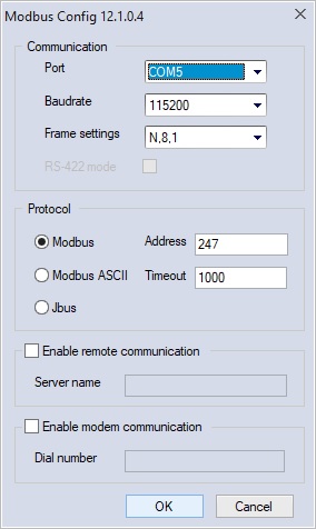
- Select Modbus protocol, click on Activate button and then on Properties button, the settings dialog will appear; configure it as shown in the image below:
- Click Ok
- Now from the main menu bar, choose On-line -> Connect
- Now, in the right-lower corner of the application window, you should see a green rectangle with the word CONNECTED written inside.
Ethernet connection
It is possible to connect the Nucleo board via Ethernet; just refer to the following steps:
- Connect to Ethernet LAN plugging cable into CN14 connector.
- Open LogicLab
- Click Scan Network… button
- If Nucleo board is recognized, you should see this results table:
- By default, IP address is assigned by DHCP
- Click on the (+) button to automatically create a new nucleo project with the right communication settings
- From the main menu bar choose On-line -> Connect
- Now, in the right-lower corner of the application window, you should see a green rectangle with the word CONNECTED written inside.
Modify ethernet communication settings
If the IP address cannot be correctly assigned by DHCP, it is possible to manually configure a fixed IP address for the Nucleo board. See the following instruction:
- Connect USB cable into CN1 connector
- Open SoftTune
- Create new Nucleo_F767ZI project
- From the menu bar choose Target -> Communication settings
- Select Modbus protocol, then click on Activate and then click on Properties
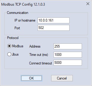
- Configure the Modbus setting as shown in the following image (specify the USB virtual COM port as recognized by your system):
- Click OK
- Click on the connection Icon
- In the bottom-right corner of the application window, you should see a green rectangle with CONNECTED written inside
- Inside the parameters tree, select All Parameters -> Communication -> Configure TCP IP address, and specify the desired IP address (this should write the parameter inside the target)
- Save parameters and reboot (from the menu bar choose Target -> Save parameter, then Target -> Device reboot
- Connect LogicLab to target via Ethernet (see 1.2 Ethernet connection)
Peripheral connection
| Peripheral | Connector | Description | Usage |
|---|---|---|---|
| Ethernet | CN14 | RJ45 port | Modbus TCP slave |
| USB | CN1 | USB-RS232 virtual port | Modbus RTU slave |
| GPIO - Out | CN12 – Pin 11 (PA5) | GPIO digital output pin | I/O |
| GPIO - Out | CN12 – Pin 13 (PA6) | GPIO digital output pin | I/O |
| GPIO - In | CN12 – Pin 23 (PA8) | GPIO digital input pin | I/O |
| GPIO - In | CN12 – Pin 21 (PA9) | GPIO digital input pin | I/O |
| CAN Rx | CN11 – Pin 57 (PD0) | CAN Rx signal | CAN Open master |
| CAN Tx | CN11 – Pin 55 (PD1) | CAN Tx signal | CAN Open master |
| USART1 Rx | CN12 – Pin 26 (PB15) | RS485 Rx signal | Modbus RTU master |
| USART1 Tx | CN12 – Pin 28 (PB14) | RS485 Tx signal | Modbus RTU master |
| USART1 DE | CN12 – Pin 12 (PA12) | RS485 Direction enable signal | Modbus RTU master |
Firmware upgrade
This is the procedure to prepare Nucleo F767ZI demo board to run Axel PLC.
N.B: all data on the flash will be erased, that means license key will be erased too.
If the target has been already licensed please be sure to have the license key available. You can read it from target using SoftTune before proceeding with the target upgrade.
- Download “STM32 ST-LINK Utility” application from ST official website at the following link
https://www.st.com/en/development-tools/stsw-link004.html#get-software - Connect Nucleo F767ZI demo board to PC using USB (CN1 connector)
- Launch “STM32 ST-LINK Utility”
- Connect to target (Target -> Connect)
- Erase the flash (Target -> Erase chip)
- Prepare to download (Target -> Program & Verify)
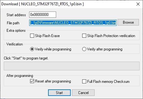
- Choose the new firmware (Select the new firmware file from Axel Installation folder, for example "C:\Program Files (x86)\Axel PC Tools\Catalog\Nucleo_F767ZI_1p0\Firmware\NUCLEO_STM32F767ZI_RTOS_1p0.bin")
- Execute the download (Click Start)
Plugin development
With Nucleo F767ZI demo board, is possible to write a user plugin to add custom functionalities to default implementation.
Plugin development allows the user to add:
- Embedded functions
- Datablocks
- Callbacks related to events
Users can develop a plugin library project with its own implementation and run it together with the already available firmware core functions.
Nucleo firmware source demo project is available for STM32 F767ZI demo board.
Firmware source consist of four project:
- NUCLEO_STM32F767ZI_RTOS – main project
- Contains .ioc project file for ST code generation
- Main PLC porting feature
- Database
- Modbus TCP slave communication stack
- TCP scan support for target identification
- COPMLib – lib project
- The CANopen master project
- ModbusRTULib – lib project
- The Modbus RTU master/slave project
- IOPluginLib – lib project
- IO Plugin sample project
IOPluginLib is here described in details as explanation on how it is possible to add plugins to your project.
IOPluginLib user sample plugin
IOPluginLib is provided as sample plugin for Nucleo demo board to show how to do a plugin with custom user functionalities.
- This plugin is used to manage 4 GPIOs: 2 inputs + 2 outputs in this way
- GPIO configuration set at startup
- I/O datablocks are published to LogicLab
- Inputs are read each time the task Fast is executed by system (using callback event)
- Outputs are written each time the task Fast is executed by system (using callback event)
Project settings
Sample project has been created using STM32 Cube IDE 3.0.0 as C static library empty project for STM32 F767ZITx target.
These include paths have then been added to access system and driver functions.
- "${workspace_loc:/NUCLEO_STM32F767ZI_RTOS/Drivers/CMSIS/Device/ST/STM32F7xx/Include}"
- "${workspace_loc:/NUCLEO_STM32F767ZI_RTOS/Drivers/CMSIS/Include}"
- "${workspace_loc:/NUCLEO_STM32F767ZI_RTOS/Drivers/STM32F7xx_HAL_Driver/Inc}"
- "${workspace_loc:/NUCLEO_STM32F767ZI_RTOS/Drivers/STM32F7xx_HAL_Driver/Inc/Legacy}"
- "${workspace_loc:/NUCLEO_STM32F767ZI_RTOS/Inc}"
- "${workspace_loc:/NUCLEO_STM32F767ZI_RTOS}"
- "${workspace_loc:/NUCLEO_STM32F767ZI_RTOS/Src}"
In addition, if RTOS is required by your plugin add this includes:
- "${workspace_loc:/NUCLEO_STM32F767ZI_RTOS/Middlewares/Third_Party/FreeRTOS/Source/include}"
- "${workspace_loc:/NUCLEO_STM32F767ZI_RTOS/Middlewares/Third_Party/FreeRTOS/Source/CMSIS_RTOS_V2}"
- "${workspace_loc:/NUCLEO_STM32F767ZI_RTOS/Middlewares/Third_Party/FreeRTOS/Source/portable/GCC/ARM_CM7/r0p1}"
These project defines have been defined to use the same micro and AlPlcRuntime defines of the main project. MCU GCC Compiler →Preprocessor
- STM32F767xx,
- USE_HAL_DRIVER,
- ALPLC_C_GCCARM,
- ALPLC_P_ARM_THUMB2VFP2,
- USE_STDINT_FOR_MISRA_C
IOPlugin interface description
IOPlugin public interface
IOPluginLib.h is the header plugin interface.
These functions can be called directly by system core but they are not published to LogicLab.
- bool_t GetDigitalInput(uint8_t id);
- bool_t GetDigitalOutput(uint8_t id);
- void SetDigitalOutput(uint8_t id, bool_t value);
- void IOPlugin_Init(void);
IOPluginLib.c provides the implementation of the plugin interface
IOPlugin_Init function
void IOPlugin_Init()
{
MX_GPIO_Init();
/* mandatory to force plugin interface allocation */
ALPLC_PLUGIN_ACTIVATE( IOPlugin )
}


