|
|
| Line 67: |
Line 67: |
|
| |
|
| Firmware developed and tested with STM32CubeIDE 1.3.0 | | Firmware developed and tested with STM32CubeIDE 1.3.0 |
|
| |
| == Quickstart ==
| |
|
| |
| === USB connection ===
| |
| It is possible to connect the Nucleo board via USB-Serial connection; just refer to the following steps:
| |
| * Connect USB cable into CN1 connector.
| |
| * Open LogicLab.
| |
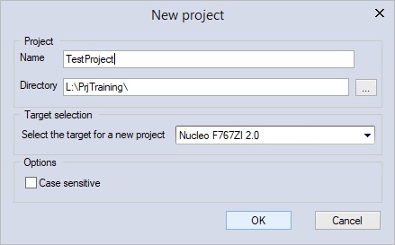
| * Create new Nucleo_F767ZI project.
| |
| * Select from LogicLab main menu bar ''On-line'' -> ''Set up communication''.
| |
| * Select ''Modbus'' protocol, click on ''Activate'' button and then on ''Properties'' button, the settings dialog will appear; configure it as shown in the image below:
| |
|
| |
| [[File:Nucleo-USBConnection1.jpg]]
| |
|
| |
| * Click ''Ok''
| |
| * Now from the main menu bar, choose ''On-line'' -> ''Connect''
| |
| * Now, in the right-lower corner of the application window, you should see a green rectangle with the word ''CONNECTED'' written inside.
| |
|
| |
| === Ethernet connection ===
| |
| It is possible to connect the Nucleo board via Ethernet; just refer to the following steps:
| |
| * Connect to Ethernet LAN plugging cable into CN14 connector.
| |
| * Open LogicLab
| |
| * Click ''Scan Network…'' button
| |
| * If Nucleo board is recognized, you should see this results table:
| |
|
| |
| [[File:Nucleo-EthScan.jpg]]
| |
|
| |
| * By default, IP address is assigned by DHCP
| |
| * Click on the (+) button to automatically create a new nucleo project with the right communication settings
| |
|
| |
| [[File:Nucleo-EthConfig.jpg]]
| |
|
| |
| * From the main menu bar choose ''On-line'' -> ''Connect''
| |
| * Now, in the right-lower corner of the application window, you should see a green rectangle with the word CONNECTED written inside.
| |
|
| |
| ==== Modify ethernet communication settings ====
| |
| If the IP address cannot be correctly assigned by DHCP, it is possible to manually configure a fixed IP address for the Nucleo board. See the following instruction:
| |
| * Connect USB cable into CN1 connector
| |
| * Open SoftTune
| |
| * Create new Nucleo_F767ZI project
| |
| * From the menu bar choose ''Target'' -> ''Communication settings''
| |
| * Select ''Modbus'' protocol, then click on ''Activate'' and then click on ''Properties''
| |
| * Configure the Modbus setting as shown in the following image (specify the USB virtual COM port as recognized by your system):
| |
|
| |
| [[File:Nucleo-USBConnection1.jpg]]
| |
|
| |
| * Click OK
| |
| * Click on the connection Icon
| |
| * In the bottom-right corner of the application window, you should see a green rectangle with ''CONNECTED'' written inside
| |
| * Inside the parameters tree, select ''All Parameters'' -> ''Communication'' -> '' Configure TCP IP address'', and specify the desired IP address (this should write the parameter inside the target)
| |
| * Save parameters and reboot (from the menu bar choose ''Target'' -> ''Save parameter'', then ''Target'' -> ''Device reboot''
| |
| * Connect LogicLab to target via Ethernet (see 1.2 Ethernet connection)
| |
|
| |
| == Peripheral connection ==
| |
| {| border="1" cellpadding="3" cellspacing="0" style="text-align:left;"
| |
| !Peripheral
| |
| !Connector
| |
| !Description
| |
| !Usage
| |
| |-
| |
| |Ethernet || CN14 || RJ45 port || Modbus TCP slave
| |
| |-
| |
| |USB || CN1 || USB-RS232 virtual port || Modbus RTU slave
| |
| |-
| |
| |GPIO - Out || CN12 – Pin 11 (PA5) || GPIO digital output pin || I/O
| |
| |-
| |
| |GPIO - Out || CN12 – Pin 13 (PA6) || GPIO digital output pin || I/O
| |
| |-
| |
| |GPIO - In || CN12 – Pin 23 (PA8) || GPIO digital input pin || I/O
| |
| |-
| |
| |GPIO - In || CN12 – Pin 21 (PA9) || GPIO digital input pin || I/O
| |
| |-
| |
| |CAN Rx || CN11 – Pin 57 (PD0) || CAN Rx signal || CAN Open master
| |
| |-
| |
| |CAN Tx || CN11 – Pin 55 (PD1) || CAN Tx signal || CAN Open master
| |
| |-
| |
| |USART1 Rx || CN12 – Pin 26 (PB15) || RS485 Rx signal || Modbus RTU master
| |
| |-
| |
| |USART1 Tx || CN12 – Pin 28 (PB14) || RS485 Tx signal || Modbus RTU master
| |
| |-
| |
| |USART1 DE || CN12 – Pin 12 (PA12) || RS485 Direction enable signal || Modbus RTU master
| |
| |-
| |
| |}
| |
|
| |
| == Firmware upgrade ==
| |
| This is the procedure to prepare Nucleo F767ZI demo board to run Axel PLC.
| |
|
| |
| N.B: all data on the flash will be erased, that means '''license key will be erased''' too. <br/>If the target has been already licensed please be sure to have the license key available. You can read it from target using SoftTune before proceeding with the target upgrade.
| |
| * Download “STM32 ST-LINK Utility” application from ST official website at the following link <br/> https://www.st.com/en/development-tools/stsw-link004.html#get-software
| |
| * Connect Nucleo F767ZI demo board to PC using USB (CN1 connector)
| |
| * Launch “STM32 ST-LINK Utility”
| |
| * Connect to target (''Target'' -> ''Connect'')
| |
| * Erase the flash (''Target'' -> ''Erase chip'')
| |
| * Prepare to download (''Target'' -> ''Program & Verify'')
| |
| * Choose the new firmware (Select the new firmware file from Axel Installation folder, for example "C:\Program Files (x86)\Axel PC Tools\Catalog\Nucleo_F767ZI_1p0\Firmware\NUCLEO_STM32F767ZI_RTOS_1p0.bin")
| |
|
| |
| [[File:Nucle-FWUpgrade1.jpg]]
| |
|
| |
| * Execute the download (Click ''Start'')
| |
|
| |
| == Plugin development ==
| |
| With Nucleo F767ZI demo board, is possible to write a user plugin to add custom functionalities to default implementation.
| |
|
| |
| Plugin development allows the user to add:
| |
| * Embedded functions
| |
| * Datablocks
| |
| * Callbacks related to events
| |
|
| |
| Users can develop a plugin library project with its own implementation and run it together with the already available firmware core functions. <br/>Nucleo firmware source demo project is available for STM32 F767ZI demo board.
| |
|
| |
| Firmware source consist of four project:
| |
| * NUCLEO_STM32F767ZI_RTOS – main project
| |
| ** Contains .ioc project file for ST code generation
| |
| ** Main PLC porting feature
| |
| ** Database
| |
| ** Modbus TCP slave communication stack
| |
| ** TCP scan support for target identification
| |
| * COPMLib – lib project
| |
| ** The CANopen master project
| |
| * ModbusRTULib – lib project
| |
| ** The Modbus RTU master/slave project
| |
| * IOPluginLib – lib project
| |
| ** IO Plugin sample project
| |
|
| |
| IOPluginLib is here described in details as explanation on how it is possible to add plugins to your project.
| |
|
| |
| === IOPluginLib user sample plugin ===
| |
| IOPluginLib is provided as sample plugin for Nucleo demo board to show how to do a plugin with custom user functionalities.
| |
| * This plugin is used to manage 4 GPIOs: 2 inputs + 2 outputs in this way
| |
| * GPIO configuration set at startup
| |
| * I/O datablocks are published to LogicLab
| |
| * Inputs are read each time the task Fast is executed by system (using callback event)
| |
| * Outputs are written each time the task Fast is executed by system (using callback event)
| |
|
| |
| ==== Project settings ====
| |
| Sample project has been created using STM32 Cube IDE 3.0.0 as C static library empty project for STM32 F767ZITx target.
| |
|
| |
| These include paths have then been added to access system and driver functions.
| |
| * "${workspace_loc:/NUCLEO_STM32F767ZI_RTOS/Drivers/CMSIS/Device/ST/STM32F7xx/Include}"
| |
| * "${workspace_loc:/NUCLEO_STM32F767ZI_RTOS/Drivers/CMSIS/Include}"
| |
| * "${workspace_loc:/NUCLEO_STM32F767ZI_RTOS/Drivers/STM32F7xx_HAL_Driver/Inc}"
| |
| * "${workspace_loc:/NUCLEO_STM32F767ZI_RTOS/Drivers/STM32F7xx_HAL_Driver/Inc/Legacy}"
| |
| * "${workspace_loc:/NUCLEO_STM32F767ZI_RTOS/Inc}"
| |
| * "${workspace_loc:/NUCLEO_STM32F767ZI_RTOS}"
| |
| * "${workspace_loc:/NUCLEO_STM32F767ZI_RTOS/Src}"
| |
|
| |
| In addition, if RTOS is required by your plugin add this includes:
| |
| * "${workspace_loc:/NUCLEO_STM32F767ZI_RTOS/Middlewares/Third_Party/FreeRTOS/Source/include}"
| |
| * "${workspace_loc:/NUCLEO_STM32F767ZI_RTOS/Middlewares/Third_Party/FreeRTOS/Source/CMSIS_RTOS_V2}"
| |
| * "${workspace_loc:/NUCLEO_STM32F767ZI_RTOS/Middlewares/Third_Party/FreeRTOS/Source/portable/GCC/ARM_CM7/r0p1}"
| |
|
| |
| These project defines have been defined to use the same micro and AlPlcRuntime defines of the main project. MCU GCC Compiler →Preprocessor
| |
| * STM32F767xx,
| |
| * USE_HAL_DRIVER,
| |
| * ALPLC_C_GCCARM,
| |
| * ALPLC_P_ARM_THUMB2VFP2,
| |
| * USE_STDINT_FOR_MISRA_C
| |
|
| |
| ==== IOPlugin interface description ====
| |
| '''IOPlugin public interface'''<br/>''IOPluginLib.h'' is the header plugin interface.
| |
|
| |
| These functions can be called directly by system core but they are not published to LogicLab.
| |
| * bool_t GetDigitalInput(uint8_t id);
| |
| * bool_t GetDigitalOutput(uint8_t id);
| |
| * void SetDigitalOutput(uint8_t id, bool_t value);
| |
| * void IOPlugin_Init(void);
| |
|
| |
| ''IOPluginLib.c'' provides the implementation of the plugin interface
| |
|
| |
| '''IOPlugin_Init function'''
| |
| void IOPlugin_Init()
| |
| {
| |
| MX_GPIO_Init();
| |
| /* mandatory to force plugin interface allocation */
| |
| ALPLC_PLUGIN_ACTIVATE( IOPlugin )
| |
| }
| |
|
| |
| This function must be called in main.c before AlPlcInit() function. <br/>IOPlugin is the unique name of the plugin. This name must be same in all macro declaration of the plugin. <br/>Plugin interface is defined in this c source and here described in details.
| |
|
| |
| '''Embedded functions table'''
| |
| ALPLC_FUNCTIONS_TABLE_INI( IOPlugin ) // start table definition
| |
| // ALFCNREC_FUNC( userFunction ) // function to publish
| |
| ALPLC_FUNCTIONS_TABLE_END // end table definition
| |
|
| |
| In this case no user function have been published. Even if function table is empty the definition is mandatory. <br/>To publish functions add between ALPLC_FUNCTIONS_TABLE_INI and ALPLC_FUNCTIONS_TABLE_END macro.a series of ALFCNREC_FUNC records indicating the function to call. Functions will be published to LogicLab with the same name of the C code function name.
| |
|
| |
| '''Datablocks table'''
| |
| ALPLC_DATABLOCKS_TABLE_INI( IOPlugin ) // start table definition
| |
| ALDBREC_INPUT( 0, m_sysDigitalInputs, sizeof(m_sysDigitalInputs[0]), DBRW_R )
| |
| ALDBREC_OUTPUT( 0, m_sysDigitalOutputs, sizeof(m_sysDigitalOutputs[0]), DBRW_RW )
| |
| ALPLC_DATABLOCKS_TABLE_END // end table definition
| |
|
| |
| Datablock table definition is mandatory, starts with ALPLC_DATABLOCKS_TABLE_INI and terminate with ALPLC_DATABLOCKS_TABLE_END. <br/>In this case two datablocks have been added using macro:
| |
| * '''ALDBREC_INPUT''' to publish the digital inputs datablock as DBTY_INP datablock with index 0.
| |
| * '''ALDBREC_OUTPUT''' to publish the digital outputs datablock as DBTY_OUT datablock with index 0.
| |
|
| |
| With this kind of definitions the whole array is published. <br/>It is possible to use ALDBREC_MEMO macro to add memo datablocks with default settings or ALDBREC_EX macro to specify each setting.
| |
|
| |
| '''Callback data definition'''
| |
| ALCBKREC_DATA(OnBeforeTaskFast)
| |
|
| |
| Some callback types (high priority callbacks) requires additional definition to provide memory to AlPlcRuntime in order to manage properly callbacks. <br/>This is the case of ALCBKREC_ON_BEFORE_PLC_TASK_IO that is used to call OnBeforeTaskFast.function. ALCBKREC_DATA definition is used for this.
| |
|
| |
| See AlPlcUserPlugin.h the list of callbacks that requires this definition. If no definition is provided compile error is given.
| |
|
| |
| '''Callback table definition'''
| |
| ALPLC_CALLBACKS_TABLE_INI( IOPlugin ) // start table definition
| |
| ALCBKREC_ON_BEFORE_PLC_TASK_IO(OnBeforeTaskFast)
| |
| ALPLC_CALLBACKS_TABLE_END // end table definition
| |
|
| |
| Callbacks table definition is mandatory, starts with ALPLC_DATABLOCKS_TABLE_INI and terminate with ALPLC_DATABLOCKS_TABLE_END. <br/>In IOPlugin the only callback associated is the OnBeforeTaskFast function associated to the on before plc task IO event (that is raised periodically in task fast).
| |
|
| |
| '''Plugin definition'''
| |
| ALPLC_PLUGIN_DEFINITION( IOPlugin )
| |
| This is the definition of the plugin. This definition is mandatory.
| |
|
| |
| === Add plugin to main firmware ===
| |
| If you want to create a new plugin you should start creating a library project (as explained in 4.1.1 Project settings), you should provide the plugin definition as explained in the sample project. See 4.3 User plugin definition for more information.
| |
|
| |
| Once you got your plugin library you can link it from main Nucleo firmware project:
| |
| * Project properties -> C++ Build -> Tool Settings. MCU GCC Linker -> Libraries <br/>Libraries box: Add your plugin library here
| |
| * Project properties -> C++ Build -> Tool Settings. MCU GCC Linker -> Libraries <br/>Libraries search path box: Add the path of the plugin library
| |
| * In main.c #include the file “yourPluginLib.h” where the init function is declared. <br/>The init function is the function that call the ALPLC_PLUGIN_ACTIVATE function. <br/>In the IOPluginLib sample is the IOPlugin_Init function.
| |
| * In main.c go to StartMainTask function and add the init function call before AlPlcInit call.
| |
|
| |
| === User plugin interface ===
| |
|
| |
| ==== Plugin definition ====
| |
| {| border="1" cellpadding="3" cellspacing="0" style="text-align:left;"
| |
| !#macro
| |
| !Description
| |
| |-
| |
| | ALPLC_FUNCTIONS_TABLE_INI(plugin) || Start your function table plugin definition with this macro. <br/>Plugin is the univoque plugin name.
| |
| |-
| |
| | ALFCNREC_FUNC(userFunction) || This is the record to publish into table a user function. <br/>The function is published with the same name of the function indicated.
| |
| |-
| |
| | ALPLC_FUNCTIONS_TABLE_END || End of function table
| |
| |-
| |
| | ALPLC_DATABLOCKS_TABLE_INI(plugin) || Start your datablock table plugin definition with this macro. <br/>Plugin is the univoque plugin name.
| |
| |-
| |
| | ALDBREC_INPUT(dbId, var, sizeEl, rw) || Add input datablock record with default options (no img flag, TRGDB_USER flag). <br/>dbId: datablock id <br/>var: the name of the variable/array variable <br/>sizeEl: the size of the basic element to publish. <br/>rw: DBRW_R, DBRW_RW, DBRW_W
| |
| |-
| |
| | ALDBREC_OUTPUT(dbId, var, sizeEl, rw) || Add output datablock record with default options (no img flag, TRGDB_USER flag). <br/>dbId: datablock id <br/>var: the name of the variable/array variable <br/>sizeEl: the size of the basic element to publish. <br/>rw: DBRW_R, DBRW_RW, DBRW_W
| |
| |-
| |
| | ALDBREC_MEMO(dbId, var, sizeEl, rw) || Add memo datablock record with default options (no img flag, TRGDB_USER flag). <br/>dbId: datablock id <br/>var: the name of the variable/array variable <br/>sizeEl: the size of the basic element to publish. <br/>rw: DBRW_R, DBRW_RW, DBRW_W
| |
| |-
| |
| | ALDBREC_EX(img, type, dbId, addr, numEl, sizeEl, rw, flags) || Add datablock record specifying all options. <br/>img: 0 no process image, 1 process image <br/>type: DBTY_INP, DBTY_OUT, DBTY_MEMO <br/>dbId: datablock id <br/>addr: the physical address of the variable to publish <br/>numEl: the number of elements to publish <br/>sizeEl: the size of each element in bytes <br/>rw: DBRW_R, DBRW_RW, DBRW_W <br/>flag: TRGDB_EMPTY, TRGDB_USER, TRGDB_RETAIN
| |
| |-
| |
| | ALPLC_DATABLOCKS_TABLE_END || End of datablock table
| |
| |-
| |
| | ALCBKREC_DATA(func) || This definition must be provided for each high priority callback function that will be indicated in callback table. <br/>If you want to use one of this macro callbacks: <br/>ALCBKREC_ON_BEFORE_PLC_TASK_IO, <br/>ALCBKREC_ON_AFTER_PLC_TASK_IO, <br/>ALCBKREC_ON_BEFORE_PLC, <br/>ALCBKREC_ON_AFTER_PLC. <br/>You need to declare its data before. <br/>func: is the name of the callback function
| |
| |-
| |
| | ALPLC_CALLBACKS_TABLE_INI(plugin) || Start your callback table plugin definition with this macro. <br/>Plugin is the univoque plugin name.
| |
| |-
| |
| | ALCBKREC_ON_BEFORE_ALPLCINIT(func) || Called once at the beginning of ALPLCINIT function
| |
| |-
| |
| | ALCBKREC_ON_AFTER_ALPLCINIT(func) || Called once at the end of ALPLCINIT function
| |
| |-
| |
| | ALCBKREC_ON_BEFORE_ALPLCMANAGE(func) || Called each time at the beginning of ALPLCMANAGE function
| |
| |-
| |
| | ALCBKREC_ON_BEFORE_START_TASKS(func) || Called just before start condition set, param indicates swap mode
| |
| |-
| |
| | ALCBKREC_ON_BEFORE_STOP_TASKS(func) || Called just before stop condition set
| |
| |-
| |
| | ALCBKREC_ON_AFTER_STOP_TASKS(func) || Called just after stop condition managed
| |
| |-
| |
| | ALCBKREC_ON_BEFORE_PLC_TASK_IO(func) || Called each time from IO/FAST task before PLC execution. <br/>Callback is executed even if PLC is not ok <br/>NB: require ALCBKREC_DATA definition
| |
| |-
| |
| | ALCBKREC_ON_AFTER_PLC_TASK_IO(func) || Called each time from IO/FAST task after PLC execution. Callback is executed even if PLC is not ok <br/>NB: require ALCBKREC_DATA definition
| |
| |-
| |
| | ALCBKREC_ON_BEFORE_PLC(func) || Called each time before PLC execution, callback param indicates task id <br/>To get the task id: uint16_t task_id = (uint16_t)(addr_t)cbk_param <br/>NB: require ALCBKREC_DATA definition
| |
| |-
| |
| | ALCBKREC_ON_AFTER_PLC(func) || Called each time after PLC execution, callback param indicates task id <br/>To get the task id: uint16_t task_id = (uint16_t)(addr_t)cbk_param <br/>NB: require ALCBKREC_DATA definition
| |
| |-
| |
| | ALCBKREC_ON_END_PLC_LOAD(func) || Called after end plc load. Indicate the result of the load. <br/>To get the load result: alplc_cbk_on_end_plc_load_param * param = (alplc_cbk_on_end_plc_load_param *)cbk_param;
| |
| |-
| |
| | ALPLC_CALLBACKS_TABLE_END || End of callback table
| |
| |-
| |
| | ALPLC_PLUGIN_DEFINITION(plugin) || This is the definition of the header struct that is managed by AlPlcRuntime. <br/>This definition require the user to implement these definitions: <br/>ALPLC_PLUGINS_HEADER_SECTION, <br/>ALPLC_PLUGINS_HEADER_SECTION_START, <br/>ALPLC_PLUGINS_HEADER_SECTION_END
| |
| |-
| |
| | ALPLC_PLUGIN_DECLARE(plugin) || The declaration of the plugin header
| |
| |-
| |
| | ALPLC_PLUGIN_ACTIVATE(plugin) || Mandatory call to make at init time to force plugin header table allocation.
| |
| |-
| |
| |}
| |
|
| |
| [[Category:Supported boards]]
| |