LLExec CANopen Master: Difference between revisions
| Line 812: | Line 812: | ||
|- | |- | ||
|Source EDS | |Source EDS | ||
* click on ''Choose..'' button to select EDS file. | |* click on ''Choose..'' button to select EDS file. | ||
* if file is a valid EDS file it is loaded and edit boxes are filled with values. | * if file is a valid EDS file it is loaded and edit boxes are filled with values. | ||
|- | |- | ||
Revision as of 15:00, 3 November 2020
Overview
LLExec CANopen master integrated configuration tool allow you to configure a network of slaves compliant to the DS301 CANopen standard.
Supported features
- Import EDS
- Automatic PDO mapping configuration generation
- Two distinct networks supported
- Slave parametrization definition
- Mandatory slaves management (stop entire network in case of loss)
- Not mandatory slave can be re-attached after its loss
- Node guarding protocol supported
- Heartbeat protocol supported in both directions: master to slaves, slave to master
- Sync PDO data exchange
- Cyclic PDO data exchange
- Event PDO data exchange
- Sync network based on sync
- SDO scheduling
- Diagnostic structures for master and slave
- PLC function calls to send SDO requests
- Multiple master implementation supported
Master configuration
General settings configuration

- Click on CANopen node on the tree view to see "CANopen Configuration" main page
Mode
| Field | Description |
|---|---|
| Not used | Select this option to disable the CANopen master |
| Master | Enable CANopen master. Configuration to be applyed will be downloaded together with PLC download |
- Click on Master option to see other configuration boxes
Baudrate
| Field | Description |
|---|---|
| Static Baudrate | Select CANopen network baudrate from the available baudrate list
|
| Parametric Baudrate (*) | Baudrate is specified at runtime. Define in your project an UDINT PLC variable and bind in Baudrate Var (UDINT) box. |
(*) This option is not always available
Master Settings
| Field | Description | Default value |
|---|---|---|
| Static Node ID | Univoque network node id is assigned to Master in static way. |
Default value: 127 Allowed values: 1 to 127 |
| Parametric Node ID (*) | Master node id is specified at runtime. Define in your project an USINT PLC variable and bind in Node ID Var (USINT) box. |
The value in the variable at PLC startup (1 to 127) will be used as master node id |
| Heartbeat time (ms) | The master producer heartbeat time in ms. If zero no heartbeat is sent by master. |
Default value: 0 No heartbeat |
| Sync COBID | The COBID value if sync mode is configured for master. |
Default value: 128 (0x80) |
| Sync Cycle (ms) | The period between two sync. Must be equals to or multiple ot task I/O period. |
Default value: 0 Sync is not sent by master |
(*) This option is not always available
Add slaves to master
First of all select Master option in Mode fieldset. Then it is possible to add slaves to the master network. This can be done in two ways:
 A) Right click
 - Right click on the resources tree on CANopen node
 - Click on Add option
 - Catalog box with all available slaves will be shown
   This includes Generic CANopen device and other CAN custom slave device (see Import EDS section)
 - Click on the slave you want to add, then click on Select button
 - A child node of the CANopen node will appear on the resources tree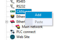
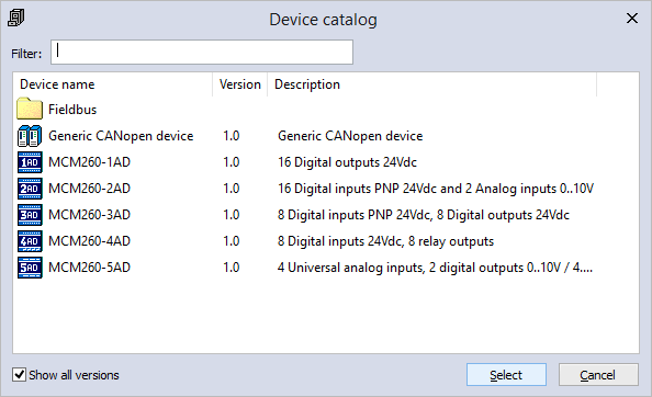


B) Drag & drop
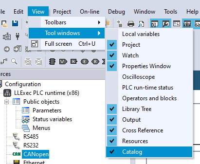
- Be sure Catalog box is shown (View -> Tool windows -> Catalog)
This includes Generic CANopen device and other CAN custom slave device (see Import EDS section)
- Drag an item from Catalog over CANopen tree node
- A child node of the CANopen node will appear on the resources tree

Slaves
Generic slave
- Generic slave node Generic CANopen device has no object dictionary.
- Objects to exchange are completely defined by user in parametrization and PDO data exchange configuration.
- Any available data exchange and configuration property can be selected by user.
- To perform slave configuration user must know slave object dictionary, data exchange and configuration limitations.
Custom slave
- Custom slave node contains all the object dictionary definitions and data exchange informations.
- Objects to exchange are already defined and can be selected for parametrization and PDO data exchange configuration.
- Only available data exchange and configuration property can be selected by user.
- It can be created by user in two ways:
Import EDS
EDS file is a standard descriptor of the slave usually released by CANopen slave vendor See Import EDS section for details
CAN custom editor
User can define by his own slave object dictionary See CAN custom editor section for details
Slave configuration
Slave configuration depends on the main type of the slave (generic or custom)
General basic configuration is quite the same on both types and it is here described.
General
Click on CANopen child node on the tree view to see "xxx Configuration" main page
Network settings
Network settings section describes the main settings of the node into network and how it is controlled by master

| Field | Description | Default value |
|---|---|---|
| Static Node Number | Univoque network node id is assigned to current slave in static way. Allowed values: 1 to 127. |
Default value: 1 |
| Parametric Node Number (*) | Node number is specified at runtime. Define in your project an USINT PLC variable and bind in Node Number Var (USINT) box. |
The value in the variable at PLC startup (1 to 127) will be used as current slave node id. |
| Node Guard Period (ms) | Enter a value > 0 to use node guarding as network control protocol (this requires Life time Factor > 0 too). Using this kind of configuration master sends a 0x700+$NODEID RTR message every Node Guard Period (ms) to slave node to get slave status. |
Default value: 200 |
| Life time Factor | Enter a value > 0 to use node guarding as network control protocol (this requires Node Guard Period (ms) > 0 too). If master has no node guarding answer from slave node for Life time Factor consecutive times, master set node to missing status. |
Default value: 3 |
| Boot time elapsed (ms) | At startup parametrization phase master sends NMT reset command to slave node. Slave node can take some time to reboot and be able to reply master requests. |
Default value: 10000 |
| Wait boot-up message (**) | Bootup message should be sent by slave after each reboot by CANopen standard. If flag is checked, master notice that slave is online on the network when receive its bootup message. |
Default value: checked |
| Node heartbeat producer time (ms) | Heartbeat can be used as network control protocol. To use heartbeat instead of node guarding set Node Guard Period (ms) = 0 and Life time Factor = 0. |
Default value: 0 No heartbeat control protocol configured |
| Node heartbeat consumer time (ms) | This setting can be used by slave to detect master loss. To use heartbeat instead of node guarding set Node Guard Period (ms) = 0 and Life time Factor = 0. |
Default value: 0 No heartbeat control protocol configured |
| Master heartbeat consumer time (ms) | Heartbeat can be used as network control protocol. To use heartbeat instead of node guarding set Node Guard Period (ms) = 0 and Life time Factor = 0. |
Default value: 0 No heartbeat control protocol configured |
| Mandatory | This flag is used to configure the master behavior in case of slave missing or slave loss. a) Not mandatory slave, slave not available on the network at startup. Master configures other available nodes and enter operational. |
Defaul value: unchecked Not mandatory slave |
| Identity Object Check (**) | It is possible to read from slave standard identity objects. Master can ask to slave these informations and check the values returned are the expected ones. |
Defaul value: unchecked No Device Info information are retrieved |
(*) This option is not always available
(**) Generic slave configuration only
Device Info
Device info box is always available for Custom slaves. For Generic slave check Identity Object Check in Network box.

| Field | Description | Default value |
|---|---|---|
| Device Type | This value is related to standard CANopen object 0x1000.0 If any value is specified in this field, 0x1000.0 object is read at node startup configuration. |
a) Generic slave: 0 b) Custom slave: the value read from EDS file |
| Vendor ID | This value is related to standard CANopen object 0x1018.1 If any value is specified in this field, 0x1018.1 object is read at node startup configuration. |
a) Generic slave: 0 b) Custom slave: the value read from EDS file |
| Product Code | This value is related to standard CANopen object 0x1018.2 If any value is specified in this field, 0x1018.2 object is read at node startup configuration. |
a) Generic slave: 0 b) Custom slave: the value read from EDS file |
| Revision | This value is related to standard CANopen object 0x1018.3 If any value is specified in this field, 0x1018.3 object is read at node startup configuration. |
Default value: 0 |
| Serial | This value is related to standard CANopen object 0x1018.4 If any value is specified in this field, 0x1018.4 object is read at node startup configuration. |
Default value: 0 |
PDO Mapping
PDO Auto Mapping configurator feature allows the user to automatically generate parametrization to match desired PDOs (Process Data Object) data exchange.

It is possible to enable PDO Auto Mapping configuration only if slave node support Variable PDO mapping.
Variable PDO mapping is the CANopen feature in which master sends configuration SDO to configure PDOs objects to be exchanged.
In Generic slave this field is always checkable. User must know if slave actually support Variable PDO mapping.
In Custom slave this field is available only if Variable PDO mapping is actually supported by slave.
If PDO Auto Mapping is checked:
- Configurator automatically generates parametrization SDO to configure PDOs data exchange.
- Configuration is generated to configure what is entered into PDO Tx - Input and PDO Rx - Output grids.
- Only objects involved in PDOs data exchange configuration are automatically changed.
- Other parametrization objects are not affected.
If PDO Auto Mapping is unchecked:
- Configurator do not modify current parametrization generated at the time.
N.B.: If you need to modifiy SDOs sequence in Parametrization, add some other param object into this sequence for any reason remember to uncheck PDO Auto Mapping.
PDO Tx communication settings
PDO Tx communication settings is related to the PDO Tx transmission modes configuration.
- This box can be used to configure the transmission mode of the PDOs Tx sent by the slave.
- This setting involves all the configured PDOs Tx.
- This setting configure CANopen objects Transmission Type (es: 0x1800.2 for PDO TX 1) and Event Timer (es: 0x1800.5 for PDO TX 1) objects.

| Option | Description |
|---|---|
| USER DEFINED Mode | Select this value if you want to specify different transmission types mode for any PDO used. The configuration rows entered into Parametrization table are not modified by configurator. |
| SYNC Mode | PDO is sent by slave every time slave receive a SYNC message from master. For every PDO Tx configured, related Transmission Type object with value 1 is entered into Parametrization table. |
| EVENT Mode | PDO is sent by slave every time something change into PDO data. For every PDO Tx configured, related Transmission Type object with value 255 is entered into Parametrization table. |
| CYCLIC Mode | PDO is sent by slave every time interval specified in the field. For every PDO Tx configured, related Transmission Type object with value 255 is entered into Parametrization table. |
PDO Rx communication settings
PDO Rx communication settings is related to the PDO Rx transmission modes configuration.
- This box can be used to configure the transmission mode of the PDOs Rx sent by master to the slave.
- This setting involves all the configured PDOs Rx.
- This setting configure CANopen objects Transmission Type (es: 0x1400.2 for PDO RX 1) objects.

| Option | Description |
|---|---|
| USER DEFINED Mode | Select this value if you want to specify different transmission types mode for any PDO used. The configuration rows entered into Parametrization table are not modified by configurator. |
| SYNC Mode | PDO is always sent by master just before SYNC message is sent. For every PDO Rx configured, related Transmission Type object with value 1 is entered into Parametrization table. |
| EVENT Mode | PDO is sent by master every time something change into PDO data. For every PDO Rx configured, related Transmission Type object with value 255 is entered into Parametrization table. |
Parametrization
Click on Parametrization tab, the grid in which all user parameters are listed will be shown.

If no PDOs are defined, you will see an empty grid.
If you check in General slave tab PDO Auto Mapping and/or set PDO Tx/Rx communication settings with a value different from USER DEFINED Mode you will see this grid automatically populated by configurator when you add PDOs.
You can add other parameters, modify the parameter value, modify the order of the rows.
Each row in this grid is a parameter for the slave that is written via SDO (Service Data Object).
At network startup (but also each time the node is lost and reattached by master) the master send to the slave node the whole parameters list writing SDOs in the specified order.
In this way PDOs configuration and transmission settings, and other custom slave parameters are set before entering operational.
Toolbar buttons
Add
- click to add an object into the parameters list.
a) Custom slave
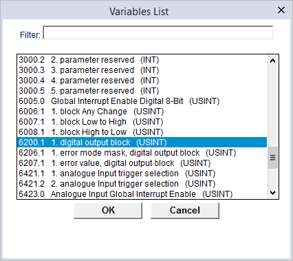
- a list with all available dictionary objects appears.
- select the parameter to add.
 b) Generic slave
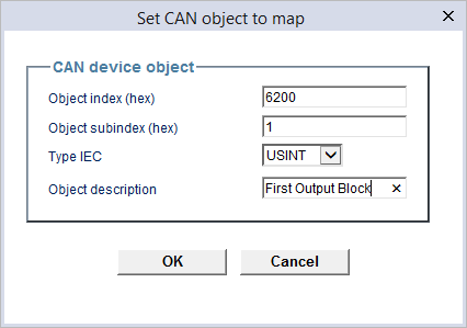
- an input dialog appear. Enter values:
Object index (hex): the parameter index, es: 6200
Object subindex (hex): the parameter subindex, es: 1
Type IEC: the type of the parameter, es: USINT
Object description: the description of the object, es: First Output Block
b) Generic slave
- an input dialog appear. Enter values:
Object index (hex): the parameter index, es: 6200
Object subindex (hex): the parameter subindex, es: 1
Type IEC: the type of the parameter, es: USINT
Object description: the description of the object, es: First Output Block
 - click ok
- a new row will be added at the end of the list with the selected object
Remove
- select the parameter row to remove
- click Remove to remove the selected row
Up
- select the parameter row to move up
- click Move to move up the selected row
Down
- select the parameter row to move down
- click Move to move dwon the selected row
- click ok
- a new row will be added at the end of the list with the selected object
Remove
- select the parameter row to remove
- click Remove to remove the selected row
Up
- select the parameter row to move up
- click Move to move up the selected row
Down
- select the parameter row to move down
- click Move to move dwon the selected row


Parametrization table
| Column | Description | Field |
|---|---|---|
| Object Name | The name of the parameter. |
Read only |
| Index | The index of the object (in hex format). |
Read only |
| SubIndex | The subindex of the object (in hex format). |
Read only |
| Type | The IEC type of the parameter. |
Read only |
| Value | The value to be written into slave for the parameter. |
Input field. The value can be specified as dec base (es: 4096), or in hex base (es: 0x1000) |
| Timeout | The timeout t expressed in ms. Master SDO write error if no slave answer in t ms. |
Input field. Default: 100 ms. |
PDO Tx - Input
Click on PDO Tx - Input tab, the grid in which enter TPDOs configuration will be shown.

PDO Tx or TPDOs are the PDO transmitted by slave to master. So they are use to get process values and other status from the slave.
If no TPDOs are defined, you will see an empty grid.
In Custom slave node mode, default TPDOs configuration can be already available.
TPDOs can be here configured, you can modify the way in which they are composed and of course make the PLC variables mapping on it.
Toolbar buttons
 Add
   - click to add an object to an existing or a new PDO.
   a) Custom slave
     - a list with all available dictionary object appear(*)
     - check Split single bits if you want to generate one row for each bit.
     - select the parameter to add.
   b) Generic slave
     - an input dialog appear. Enter values:
       Object index (hex): the parameter index, es: 6000
       Object subindex (hex): the parameter subindex, es: 1
       Type IEC: the type of the parameter, es: USINT
       Split single bits: if checked generate one row for each bit in type. In this example generates 8 rows to map 8 BOOL variables
       Object description: the description of the object, es: First Input Block
   - click ok.
   - a new row will be added at the end of the list with the selected object.
   The new item is added after the last element of the last PDO (see Bit' column field).
   If it does not fit into last PDO (max 64 bit) it is automatically put in a new PDO (see PDO column field).

 (*) items in this list must be defined as mappable on PDO in EDS configuration file.

 Remove
   - select the PDO object element to remove.
   - click Remove.
   If the element removed is a splitted bit row, the entire type block is removed.
   PDOs are not refactored after remove. An hole in PDO configuration can remain and should be filled or other elements must me updated (by PDO and Bit field setting).

 Assign
   - select the row in which to map an IEC variable
   - click Assign
   - a list with all available variables is shows: global variables, same size of the PDO element type
   - if you click on Show all checkbox mapped variables of the same size of the PDO element type appears in the list
   - select variable to use
   - click OK
   Selected variable is put into Label field. You can use this variable into PLC code. This variable value will be sent by master in TPDO.
   If variable is global, it is mapped into fieldbus datablock. See DataBlock field.
   If variable was already mapped, the address remains the same. See DataBlock field. Mapped variable cannot be on a readonly datablock.

 UnAssign
   - select the row in which an IEC variable to remove from mapping is set (Label is specified)
   - click UnAssign
   Label field and DataBlock fields are now empty.
   Unassigned variable is set as automatic variable.
PDO Tx - Input table
| Column | Description | Edit mode |
|---|---|---|
| Idx | The index (in hex format) of the CANopen slave object dictionary item that will be exchanged on this PDO. | Read only |
| Sub | The subindex (in hex format) of the CANopen slave object dictionary item that will be exchanged on this PDO. | Read only |
| PDO | The number of the PDO. TPDOs and RPDOs are numbered from 1 to n. Each PDO can contain max 64 bits of process data. |
Input |
| Bit | This is the bit offset position (0 to 63) from which the mapped variable take place. BOOL variable can be mapped on a splitted data type at each bit position.
No holes inside a PDO must be left. Example
|
Input |
| COBID | COBID is the univoque object id assigned to PDO for data exchange. COBID are assigned automatically in network configuration for the first 4 standard PDOs 1, 2, 3, 4.
|
Input |
| Object Name | This is the name of the slave object that wil be exchanged. | Read only |
| Type | The IEC type of the object (and of the variable if defined in Label field) | Read only |
| Size | The size in bit of the object. | Read only |
| Label | This field is used to bind IEC variable to PDO value. This field is filled by Assign operation, is cleared by UnAssign operation.
If you clear this field leaving it empty, associated variable is unmapped from datablock, it is set as global variable. |
Input |
| DataBlock | Variable datablock address
If no variable is specified as Label this field is empty too. |
Read only |
PDO Rx - Output
Click on PDO Rx - Output tab, the grid in which enter RPDOs configuration will be shown.

PDO Rx or RPDOs are the PDO transmitted by master to slave. So they are used to set slave output or settings.
If no RPDOs are defined, you will see an empty grid.
In Custom slave node mode, default RPDOs configuration can be already available.
RPDOs can be here configured, you can modify the way in which they are composed and of course make the PLC variables mapping on it.
Toolbar buttons
 Add
   - click to add an object to an existing or a new PDO.
   a) Custom slave
     - a list with all available dictionary object appear(*).
     - check Split single bits if you want to generate one row for each bit.
     - select the parameter to add.
   b) Generic slave
     - an input dialog appear. Enter values:
       Object index (hex): the parameter index, es: 6200
       Object subindex (hex): the parameter subindex, es: 1
       Type IEC: the type of the parameter, es: USINT
       Split single bits: if checked generate one row for each bit in type. In this example generates 8 rows to map 8 BOOL variables
       Object description: the description of the object, es: First Output Block
   - click ok.
   - a new row will be added at the end of the list with the selected object.
   The new item is added after the last element of the last PDO (see Bit' column field).
   If it does not fit into last PDO (max 64 bit) it is automatically put in a new PDO (see PDO column field).

 (*) available items in mappable object list must be defined as mappable on PDO in EDS configuration file.

 Remove
   - select the PDO object element to remove.
   - click Remove.
   If the element removed is a splitted bit row, the entire type block is removed.
   PDOs are not refactored after remove. An hole in PDO configuration remains and should be filled or other elements must me updated (by PDO and Bit field setting).

 Assign
   - select the row in which to map an IEC variable
   - click Assign
   - a list with all available variables is shows: global variables, same size of the PDO element type
   - if you click on Show all checkbox mapped variables of the same size of the PDO element type appears in the list
   - select variable to use
   - click OK
   Selected variable is put into Label field. You can use this variable into PLC code. It will assume the value sent by slave with current RPDO.
   If variable is global, it is mapped into fieldbus datablock. See DataBlock field.
   If variable was already mapped, the address remains the same. See DataBlock field.

 UnAssign
   - select the row in which an IEC variable to remove from mapping is set (Label is specified)
   - click UnAssign
   Label field and DataBlock fields are now empty.
   Unassigned variable is set as automatic variable.
PDO Rx - Output table
See PDO Tx - Input table description in PDO Tx - Input section
SDO scheduling
PDOs data exchange transmission mode is scheduled by CANopen standard with well defined and strict rules.
Master, together with slave supported feature, define PDOs data exchange but it is not always possible to use PDOs as the only way to exchange data between master and slave.
This is the case is which slave has a static configuration but application requires to read or set other parameters values cyclically or when desired.
Other possible case is a lot of data must be read or written by max slave PDOs supported is reached.
In these cases it is possible to use SDO instead of PDO to read/write values with the slave.
SDO scheduling is used to configure this data exchange method via SDOs instead of PDOs.
This kind of data exchange is not deterministic and at lower priority that PDOs data exchange configuration.
Scheduler run a sort of loop over all the SDO to exchange and continues in this way processing one request at the time.
N.B.: this kind of functionality is not always available
Click on SDO Scheduling tab, the grid in which enter scheduling for read/write operations via SDO will be shown.

Toolbar buttons
 Add
   - click to add an object into the SDO scheduling list.
   a) Custom slave
     - a list with all available dictionary objects appears.
     - select the parameter to add.
   b) Generic slave
     - an input dialog appear. Enter values:
       Object index (hex): the parameter index, es: 6200
       Object subindex (hex): the parameter subindex, es: 1
       Type IEC: the type of the parameter, es: USINT
       Object description: the description of the object, es: First Output Block
   - click ok
   - a new row will be added at the end of the list with the selected object

 Remove
   - select the parameter row to remove
   - click Remove to remove the selected row

 Up
   - select the parameter row to move up
   - click Move to move up the selected row

 Down
   - select the parameter row to move down
   - click Move to move dwon the selected row

 Assign
   - select the row in which to map an IEC variable
   - click Assign
   - a list with all available variables is shows: global variables, same size of the object dictionary element type
   - if you click on Show all checkbox mapped variables of the same size of the object dictionary element type appears in the list
   - select variable to use
   - click OK
   Selected variable is put into Label field. You can use this variable into PLC code.
   If variable is global, it is mapped into fieldbus datablock.
   If variable was already mapped, the address remains the same. Mapped variable cannot be on a readonly datablock if used in Read or ReadWrite mode.

 UnAssign
   - select the row in which an IEC variable to remove from mapping is set (Label is specified)
   - click UnAssign
   Label field is now empty.
   Unassigned variable is set as automatic variable.
SDO Scheduling table
| Column | Description |
|---|---|
| Object Name | The name of the parameter. Read only field |
| Index | The index of the object (in hex format). Read only field |
| SubIndex | The subindex of the object (in hex format). Read only field |
| Type | The IEC type of the parameter. Read only field |
| Label | Parameter name |
| Direction | The direction in which parameter is exchanged using SDO. a) Read: Parameter value is read from slave. Label variable is set with readed value.
|
| Oneshot | SDO request can be triggered by PLC using a Oneshot BOOL variable. Enter in this field a variable name. This will create a BOOL variable.
|
| Polling time | If Oneshot variable has been specified this field configuration is not considered. Input Polling time value to configure scheduling. a) 0
b) 1
c) > 1 The value, indicated in ms is the polling time associated to the request. If elapsed time from last transmission is greater than specified interval, SDO request is performed. |
| Timeout | The timeout t expressed in ms. Master SDO write error if no slave answer in t ms. |
CANopen Master diagnostic
Diagnostic structures are available linking COPM.pll into LogicLab project.
Detailed description of diagnostic structures and other target blocks can be found directly in LogicLab Properties Window.
Import EDS
Import EDS is the integrated LogicLab tool that can be used to generate CANopen Custom slave devices starting from vendor released EDS file.
Import EDS is available from LogicLab --> Tool --> Import EDS.
Import EDS dialog will be shown.

Import EDS dialog
| Field | Description |
|---|---|
| Source EDS | * click on Choose.. button to select EDS file.
|
| New Name and Version | The name and the version that will be assigned to CAN Custom device. |
| Short Name | Will be used as device unique id identification |
Has variable PDO mapping
| |
Sends boot-up message at reset
| |
| Vendor Name | The vendor name of the target device registered at CiA. |
| Product Name | The product name description of the target device. |
| Revision | The revision number of the hardware. |
| Description | Device general description provided. |
| Comments | Device notes provided. |
| Number of Objects - Mandatory | Number of mandatory object dictionary items found. |
| Number of Objects - Optional | Number of optional object dictionary items found. |
| Number of Objects - Manufacturer | Number of manufacturer object dictionary items found. |
Once selected the EDS file to import, click on OK button.
If everything is ok device will be added to CANopen Custom slaves list.
It is now possible to add the new created slave to Master network configuration.
If something fails in loading or importing EDS file maybe useful to validate EDS file with an external tool (es: Vector CANeds checker) because it is possible that EDS file is not fully compliant to standard.
CAN custom editor
If no EDS file is available it is also possible to create CANopen Custom device slave using an integrated editor: CAN custom editor.
It is possible to define basic properties and slave object dictionary.
CAN custom editor is available from LogicLab --> Tool --> Run CAN custom Editor.
CANopen Custom Editor is shown and here described

Main toolbar buttons
 New
   Click to create a new CANopen Custom slave definition

 Open
   Open a CANopen Custom device file (file of this type has .PCT extension).
   Available descriptor files are usually in [LogicLab install folder]\Catalog\CANcustom.

 Save
   Save current status of editing.
   Save into [LogicLab install folder]\Catalog\CANcustom if you want this file to be used in current installation.

 Close
   When CAN custom editor is closed Catalog cache in invalidated and rebuilt.
   New created device object is available and can be added to master network.
Device Version
 Name
   The slave device name

 Version
   The version of the slave device
   Default: 1.0

 Description
   The description of the slave device
   Default: Custom CANopen device
Device Info
 Num PDO Tx
   Maximum number of TPDOs that can be configured for transmission from slave to master

 Num PDO Rx
   Maximum number of RPDOs that can be configured for reception of PDOs transmitted from master to slave

 Variable PDO mapping
   a) if checked, slave device support PDOs reconfiguration during parametrization by master
   b) if unchecked, slave device PDOs configuration is defined as static.
      Master cannot change this configuration and must be configured according to the established data exchange.

 Granularity
   Used for PDO mapping check.
   If granularity is 1 mapped object can start at each bit into PDO.
   If granularity is > 1 mapped object can start at bit offset % granularity. (es granularity 8, PDO entry can start at bit 0, 8, 16, 24, 32, 40, 48, 56)
Grid toolbar buttons
 Add
   Click to add new row into object dictionary table.
   New row is added at the bottom of the list.

 Remove
   First select row to remove
   Click remote to remove object dictionary row from table.
Grid columns
In this table is defined the whole dictionary objects of the slave.
By default, it is provided a slave dictionary objects with all the entries required to exchange 1 TPDO and 1 RPDO and to support device identification and variable PDO mapping.
 Index (hex)
   CANopen object index.
   Object must be defined according to CANopen standard.

 Subindex (hex)
   CANopen object subindex.
   The key [Index].[Subindex] must be unique.

 Label
   This is the name of the dictionary object item.

 Type
   IEC type of the dictionary object item.

 Access Type
   a) rw: object can be read and written.
   b) ro: object can be only read.
   c) wo: object can be only written.

 Def. value
   Default value, specify a valid value according to the object.
   If Show def value in Hex is checked default value is shown in hexadecimal format.
   If Show def value in Hex is unchecked default value is shown in decimal format.
   $NODEID+0x000 format can be used to define dinamic assignment of COBID to PDO (es: $NODEID+0x180 for the first TPDO in 0x1800.1 COB-ID entry).

 PDOMapping
   False: current entry will be not available for PDOs data exchange configuration.
   True: current entry will be available for PDOs data exchange configuration.

 Description
   Additional description field