Configuration: Modbus RTU
Resources Tab
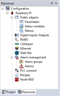
Resources tab allow you to define parameters and status variables to publish to other devices; fieldbus network configuration, alarms definitions, recipes, I/O mappings and so on.
If your target board supports Modbus RTU, you should have a serial port node, in your project tree, that can be configured to do so.
RS485 port can be used to configure your target as Modbus RTU Master (to control a network of slaves that answer to your Modbus requests) or as Modbus RTU Slaves (in this case another device will make requests to read or write parameters ad status variables that you have previously defined as Public Objects).
In your LogicLab release, the Resource tab may look quite different from the one described here; that depends on the target supported features and on the software customization desired by the client.
Modbus RTU Master configuration
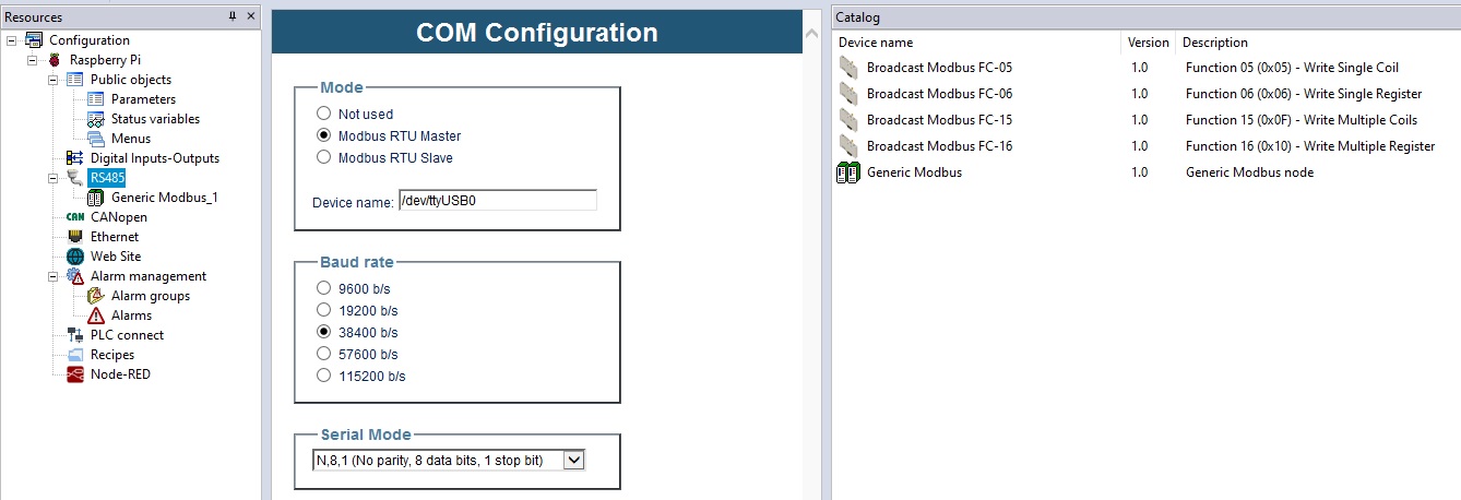
Click on the RS485 node in your project tree, to display the following configuration window in the main area.
You can decide how to configure the resource by choosing among:
- Not used (dafault)
- Modbus RTU master
- Modbus RTU slave
Choose Modbus RTU master to configure the serial port as the Master of a Modbus RTU network.
After choosing a working configuration, you'll be allowed to choose the setting parameters (baudrate and serial mode).
You'll also be allowed to define you own device network selecting them from the catalog window and dragging them under the RS485 node, or by right-clicking the RS485 node, choosing Add and selecting the desired device.
If the Catalog window is not visible, you can enable it by selecting menu View -> Tool windows -> Catalog.
By dragging (or adding) the Generic Modbus device to the RS485 node, you can define a series of Modbus commands for exchanging, in read/write, one or more variables with a generic RTU slave device.
Otherway, if you want to define your own custom device, you can do it by selecting menu Tools -> RUn Modbus Custom Editor.
Generic Modbus Slave
After inserting a Generic Modbus node under the RS485 node, you can click it to show:
- Inside the main window, the General tab and the Parametrization tab.
- Inside the catalog window, the list of all the available Modbus commands.
The General tab allows you to set:
- Name: the name of the slave node
- Modbus address: the Modbus address of the slave node inside the RTU network
- Node number: a value used for diagnostic purpose to identify the slave node
The Parameterization tab lets you define a series of Modbus objects to be sent to the slave node at each PLC restart.
The list of objects to be sent is built with the Add and Remove buttons that appear on the Tab.
Once an object (a row of the table) is added, you have to set:
- Address: Modbus address of the object to be written
- Type: type of the object to be written
- Value: value assigned to the object to be written
- TimeOut: value of maximum time (in milliseconds) after which the operation is considered failed (default is 200 ms)
Always by dragging or adding from the catalog window, you can also assign to the slave device node, one or more Modbus commands (you may not see always all of this commands):
- Modbus FC-01(Read Coils): reading of one or more RW bits by slave node
- Modbus FC-02(Read Discrete Inputs): reading of one or more RO bits by slave node
- Modbus FC-03(Read Holding Registers): reading of one or more RW registers by slave node
- Modbus FC-04(Read Input Registers): reading of one or more RO registers by slave node
- Modbus FC-05(Write Single Coil): writing of a single RW bit on slave node
- Modbus FC-06(Write Single Register): writing of a single RW register on slave node
- Modbus FC-15(Write Multiple Coils): writing of one or more RW bits on slave node
- Modbus FC-16(Write Multiple registers): writing of one or more RW registers on slave node
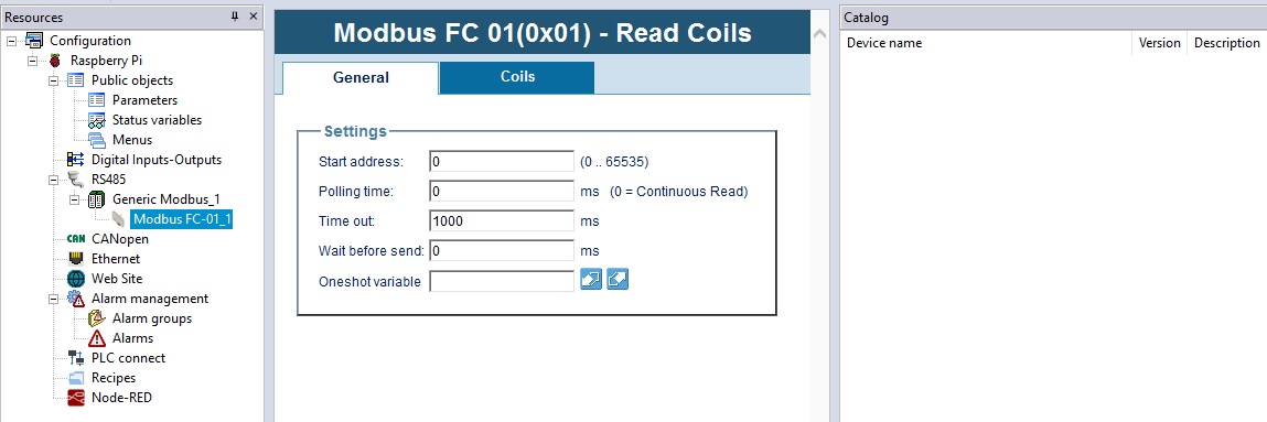
Let's suppose we add a Modbus FC-01(Read Coils) command, selecting it from the project tree, you'll see a new window in the main window with a General tab and a Coils tab (the tabs depends on the command, if it was a Modbus FC-16(Write Multiple registers) command, you would have seen a General tab and a Multiple Regs. tab).
In the General tab, you can set:
- Start address: Modbus address of the first object (coil) to be read
- Polling time: minimum interval of time (in milliseconds) to wait before executing again the command; if set to 0, the time between two commands execution depends on the PLC idle
- Timeout: value of maximum time (in milliseconds) after which the operation is considered failed (default is 1000 ms)
- Wait before send: waiting time before each command execution, doesn't count PLC idle time. This time is added to Polling time value. (Default 0)
- One shot variable: you can specify a BOOL variable that is used to trigger the sending ofthe command. When this variable is set to TRUE the command is sent, then, when the command is actually served, the variable is automatically reset by Modbus RTU master.
On the Coils tab, you can decide how many objects (coils) read with every command execution, starting from the Start address set on the General tab.
You have to assign a variable to each element (row of the table), using one of the following modes:
- usign the Assign button, choose one of the variables previously declared on the PLC (for coils only booleans are allowed). The variable will be mapped as a datablock.
- directly declare a new variable in the Label column, the variable will be mapped as a datablock boolean variable.
Modbus custom editor
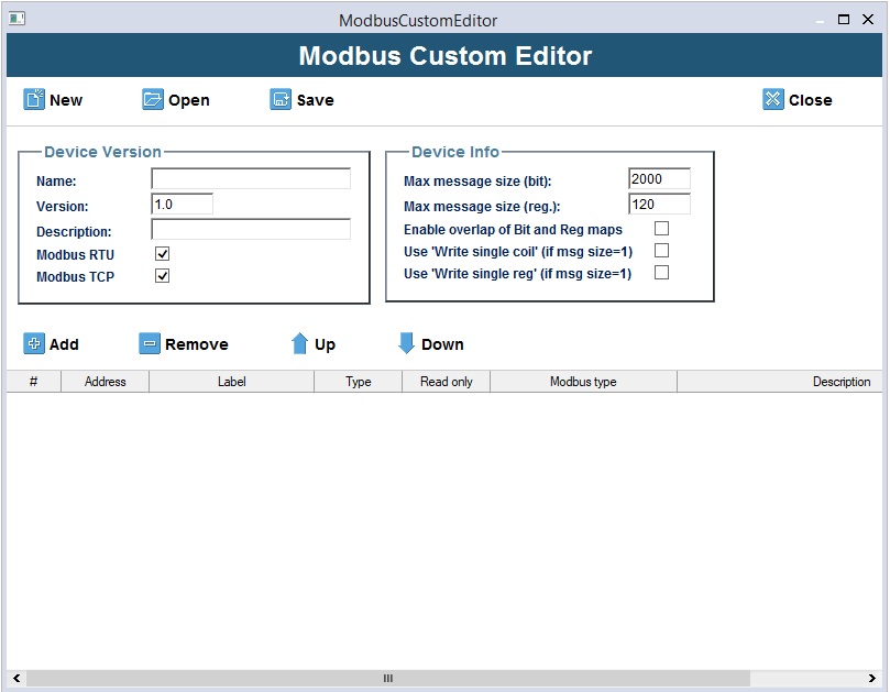
The Modbus Custom Editor is a graphic tool that lets you define the MODBUS map of a generic RTU device, allowing you to define you own device.
The file generated by this tool, that describe the device, is automatically inserted inside LogicLab Catalog window.
To execute it, select Tool -> Run Modbus custom editor.
Here's an overview of all the editor feature
- New button: lets you create a new empty custom device file.
- Open button: lets you open an already existing custom device file.
- Save button: lets you save the current custom device file.
- Close button: will close the tool.
- Name field: this is the name of this custom device, it will be visible in the Catalog window when choosing the device do add. The name must begin with a letter; if you use a number as first digit, it will be preceded automatically with a "_" character.
- Version field: lets you set the version of the custom device.
- Description field: lets you set the description of the custom device
- Modbus RTU checkbox: lets you set whether or not the custom devicecan be used in a Modbus RTU (Serial) network (it will be visible in the Catalog when seletting the RS485 node).
- Modbus TCP checkbox: lets you set whether or not the custom device can be used in a Modbus TCP (Ethernet) network.
- Max message size (bit) field: lets you set the maximum number of bits that the customdevice will be able to exchange with the Master node using a single Modbus command.
- Max message size (reg.) field: lets you set the maximum number of registers that the custom device will be able to exchange with the Master node usiing a single Modbus command.
- Enable overlap of bit and reg maps checkbox: lets you set whether or not the bit map and the custom device registers overlap (i.e., whether or not they share addresses).
- Use "Write single coil" (if msg size = 1)" checkbox: implicitly use always the "Write single coil" command when writing coils.
- Use "Write single reg" (if msg size = 1)" checkbox: implicitly use always the "Write single register" command when writing registers.
- Add button: lets you insert an object in the Modbus map of the custom device
- Remove button: lets you remove selected objects (with yellow borders) from the Modbus map of the custom device. (Keeping pressed the CTRL button allow you to select multiple rows even if not contiguous; keeping pressed the SHIFT button allow you to select multiple contiguous rows).
- Address column: lets you set the Modbus address assigned to the object in question in the slave device.
- Label column: lets you set the name of the parameter assigned to the Modbus objectin question.
- Type column: lets you set the type of parameter assigned to the Modbus object in question. Available data type are:
| Type | Description |
|---|---|
| BOOL | bit |
| SINT | 8 bit with sing |
| USINT | 8 bit without sign |
| BYTE | 8 bit (sign is insignificant) |
| INT | 16 bit with sign |
| UINT | 16 bit without sign |
| WORD | 16 bit (sign is insignificant) |
| DINT | 32 bit with sing |
| UDINT | 32 bit without sign |
| DWORD | 32 bit (sign is insignificant) |
| REAL | 32 bit |
- ReadOnly column: lets you set the access mode to the object in question (if readOnly or read/write)
- Modbus type column: lets you set the configuration of the Modbus object in question(Type and Read only columns), using the standard code provided by the Modbus communication protocol.
The configuration of Modbus type column and the Type and Read only columns are strictly correlated; any changes to one of these columns will cause automatic alignment of the others (see table below):
| Type | ReadOnly | Modbus type |
|---|---|---|
| BOOL | TRUE | Discrete Input |
| BOOL | FALSE | Coil |
| USINT | TRUE | Input register (8 bit) |
| USINT | FALSE | Holding register (8 bit) |
| BYTE | TRUE | Input register (8 bit) |
| BYTE | FALSE | Holding register (8 bit) |
| INT | TRUE | Input register (16 bit) |
| INT | FALSE | Holding register (16 bit) |
| UINT | TRUE | Input register (16 bit) |
| UINT | FALSE | Holding register (16 bit) |
| WORD | TRUE | Input register (16 bit) |
| WORD | FALSE | Holding register (16 bit) |
| DINT | TRUE | Input register (32 bit) |
| DINT | FALSE | Holding register (32 bit) |
| UDINT | TRUE | Input register (32 bit) |
| UDINT | FALSE | Holding register (32 bit) |
| DWORD | TRUE | Input register (32 bit) |
| DWORD | FALSE | Holding register (32 bit) |
| REAL | TRUE | Input register (32 bit) |
| REAL | FALSE | Holding register (32 bit) |
- Description column: lets you set the description of the Modbus object in question.
Devices in catalog
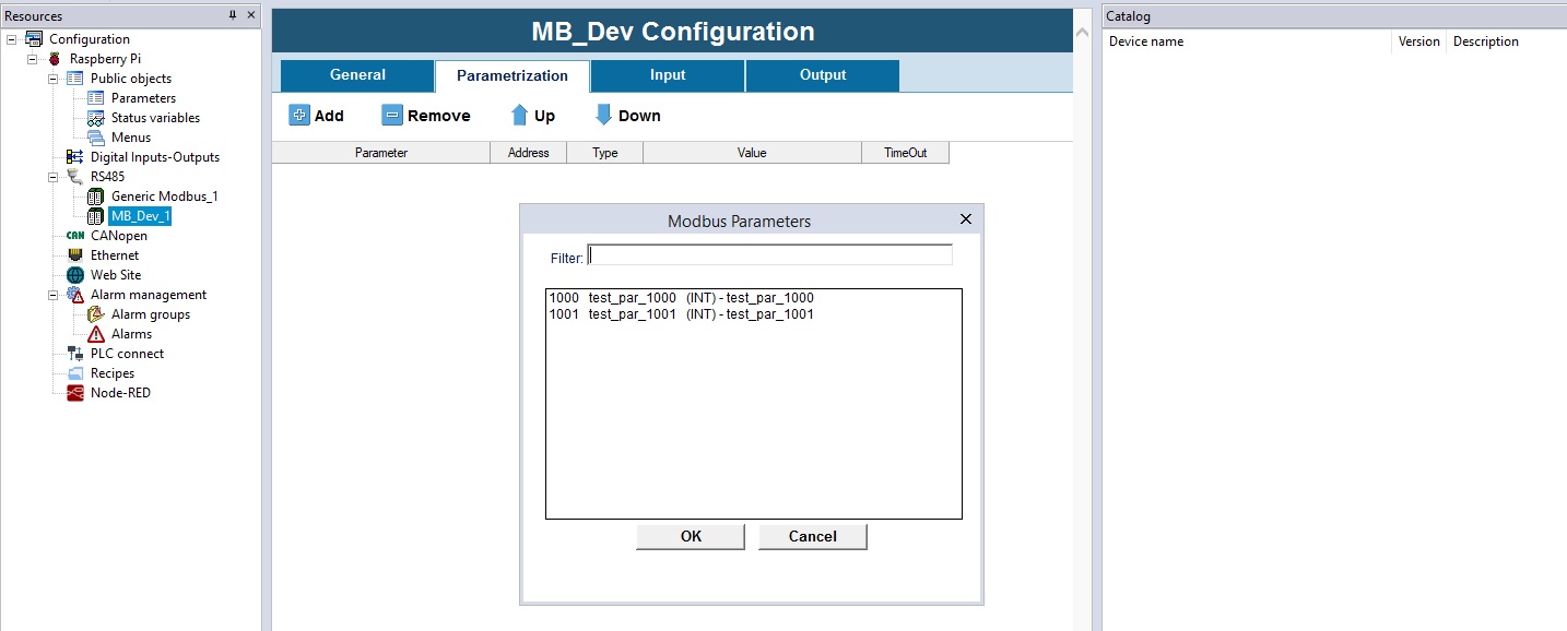
Specific devices (like custom devices) have a different interface from the Generic Modbus Slave; selecting a device node from the project tree (previously added from the Catalog window), will display teh following inside the main window:
The General tab lets you set:
- Name: name of the slave node.
- Modbus address: MODBUS address of slave node inside the network.
- Node number: value used by diagnostics tools to identify the slave node.
- TimeOut: time (ms) waited before the operation is considered failed (default = 1000 ms)
- Wait before send: time (ms) waited before executing a new operation; this value is added to the polling time of the parameter. (Default = 0 ms).
The Parameterization tab lets you define a series of Modbus objects sent to the slave node at each PLC restart.
The list of objects to be sent is built with the Add and Remove buttons that appear on the Tab.
The objects shown in the window that appears after the Add button is pushed are all (and only) RW parameters contained in the device Modbus dictionary.
You can set the order for sending parameters to the slave node by using the Up and Down buttons.
Once an object (a row) is added, you have to set:
- Value: value to be assigned to Modbus object
- TimeOut: time (ms) waited before the operation is considered failed (default = 200 ms)
The Input tab lets you define (with the Add and Remove buttons) which and how many parameters will be read by the device.
The window that appears when the Add button is pushed shows all of the available objects in the device Modbus dictionary (both RO and RW).
You can set the order for reading parameters from the slave node by using the Up and Down buttons.
You have to assign a variable to each line inserted by using one of the modes described below:
- Use the Assign button, click one of the Automatic variables (the type depends on the contents of the Type column) previously declared on the PLC.
The variable will no longer appear in the Automatic variables list but will be mapped in the appropriate datablock. - Directly declare a variable in the Label column (the type depends on the contents of the Type column); the variable will be created and mapped in the appropriate datablock.
You can also set the Polling time parameter to define the interval in milliseconds between two executions of MODBUS command; if set to 0, the time between two commands execution depends on the PLC idle
If the listed objects have:
- Contiguous Addresses
- Identical Polling time
- Homogeneous Type: USINT, BYTE, INT, UINT, WORD, DINT, UDINT, DWORD and REAL are homogeneous with regard to Modbus because they are all seen as one or more registers.
They will be grouped in a single Modbus request, subject to the maximum number of consecutive objects (bits or registers) that can be exchanged with the device in a single request.
The Output tab lets you define (with the Add and Remove buttons) which and how many parameters will be written on the device.
The objects shown in the window that appears after the Add button is pushed are all (and only) RW objects contained in the device Modbus dictionary.
You can set the order for writing these parameters on the slave node by using the Up and Down buttons.
You have to assign a variable to each line inserted by using one of the modes described below:
- Use the Assign button, click one of the Automatic variables (the type depends on the contents of the Type column) previously declared on the PLC.
The variable will no longer appear in the Automatic variables list but will be mapped in the appropriate datablock. - Directly declare a variable in the Label column (the type depends on the contents of the Type column); the variable will be created and mapped in the appropriate datablock.
You can also set the Polling time parameter to define the interval in milliseconds between two executions of MODBUS command; if set to 0, the time between two commands execution depends on the PLC idle.
If the listed objects have:
- Contiguous Addresses
- Identical Polling time
- Homogeneous Type: USINT, BYTE, INT, UINT, WORD, DINT, UDINT, DWORD and REAL are homogeneous with regard to Modbus because they are all seen as one or more registers.
They will be grouped in a single Modbus request, subject to the maximum number of consecutive objects (bits or registers) that can be exchanged with the device in a single request.
Modbus RTU Slave configuration
Configure the target board as Modbus RTU slave if you want your board to manage R/W request from a master.
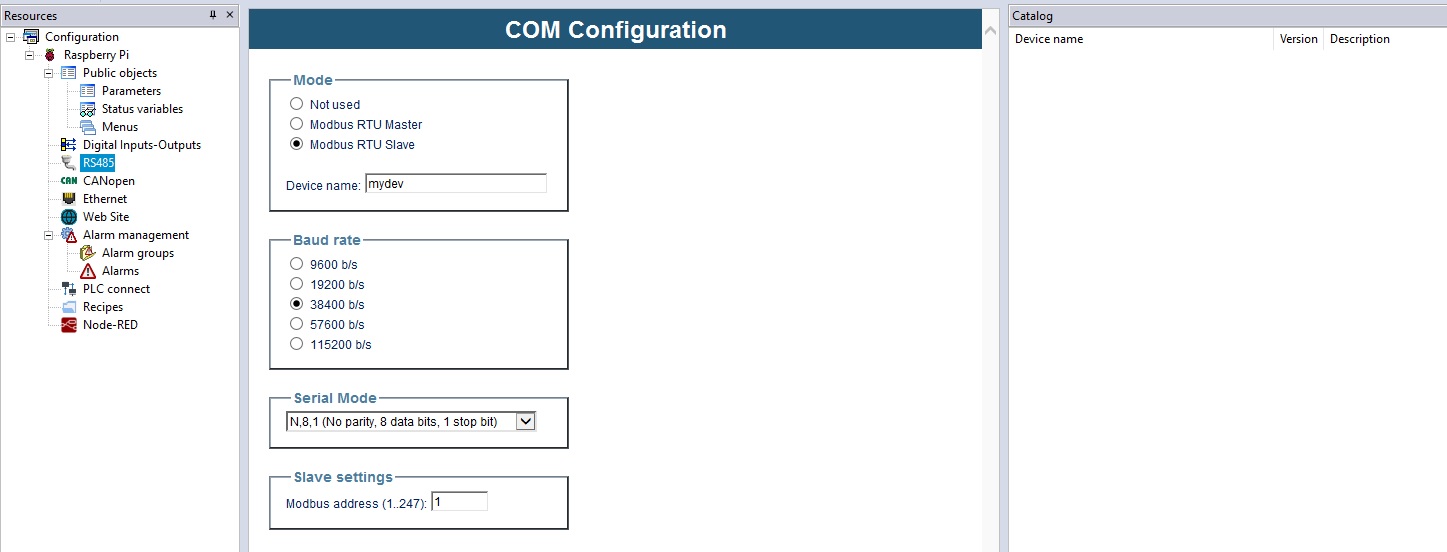
Click on the RS485 node in the project tree; a new window will appear in the main, asking you how to configure the serial port; choose Modbus RTU Slave to configure the serial port as a slave node in a Modbus RTU network.
After choosing Modbus RTU Slave, you'll be asked to insert more communication information:
- Baudrate
- Serial mode (parity check, number of databits, stop bit)
- Modbus address, node address in the Modbus network
If the serial port is a slave, the Catalog window will remain empty, you can't add a slave device to a slave node.
On the contrary, the master of the Modbus network, will be able to read and write the parameters published by your slave.
Modbus Database definition
Slave should publish a database indexed using Modbus addresses.
On your target you can have:
- Embedded database: always available on the target board and not depending on the application
- Application database: defined using LogicLab and thus different for every application
- Both: a range of Mobus addresses will be reserved for embedded parameters database definitions and a distinct range of addresses could be used for application database definitions.
Target embedded database
The provider of the target board has already defined a Modbus object dictionary and has established the address values and their meanings (match between address and correspondingparameter / status variable / input / coil) for the target.
If your target board has an on board Modbus database you can simply enable RTU slave mode to give access to the on board database.
Application database (using LLExec)
Objects that can be accessed by an external Master are defined using LogicLab itself.
You can begin defining the dictionary of published Modbus objects in the following areas:
- Parameters: where you can insert all of the objects you want to be written just once.
- Status variables: where you can insert all of the objects that can be read/written multiple times.
If you are using a target board that run Axel LLExec runtime the following screen will be displayed when you click the Parameters node:
here you can:
- use the Add button to add a new row to the table in order to link one of the published project variables. In the Address column of the table, the Add command will propose the first useful Modbus address, allowing you to change it.
- use the Remove button to remove one or more rows from the grid.
- use the Recalc button to force automatic recalculation of Modbus addresses of the selected rows, starting from address 1. This operation overwrites previous settings.
- use the Assign button to publish, in the Modbus address indicated in the Address column, one of the Automatic variables declared in the PLC project that will become part of the mapped variables (no longer on the Automatic list). If you insert (in the Name column of the table) a variable that is not one of those declared Automatic in the PLC, that variable will be inserted in the appropriate datablock.
- use the UnAssign button to remove an assignment between Modbus address and the variable mapped in the datablock; the variable will appear on the Automatic listof PLC project.
In addition to the Address and Name columns, you can also set the following columns:
- Default value: contains the initial value of the Modbus object.
- Min: contains the minimum value that can be assigned to the Modbus object in questionby the Master by means of a write operation. This limit can be a numerical constant or aparameter (i.e., one of the Modbus objects inserted in the Parameters or Status variables table).
- Max: contains the maximum value that can be assigned to the Modbus object in question by the Master by means of a write operation. This limit can be a numerical constant or a parameter (i.e., one of the Modbus objects inserted in the Parameters or Status variables table).
- Description: contains a brief description of the object.
If you choose the Status variables node, the following screen will be showed in the main area:
With regard to the buttons and columns, see the description of the Parameters area.
In this case, since the listed objects are RW, you can decide (via the Read only column) whether the object can ONLY be read or read and write by the Master.
Other Application database implementation
Database configuration interface depends on the database structure implemented on the real target.
If your target is not running Axel LLExec runtime database implementation and management could be quite different.
Your application database can be implemented in this way:
- On the target firmware, one or more datablocks have been dedicated to be used for database definition.
- A convention between Modbus addresses and data access into these datablocks is established.
- With LogicLab you can define a variable and map it on the desired datablock; its value can then be accessed by modbus (using the established convention)
Let see it with an example:
- The target board has been implemented to publish an array of 1000 WORDs, as a datablock towads LogicLab (this is your database).
- A Modbus address range from 50000 to 50999 has been reserved and dedicated to the access of the database (this is the established convention).
- If you map a WORD variable on the first element of the datablock its value can be accessed via Modbus at the address 50000, if you map it on the second element it can be accessed via Modbus at the address 50001, and so on; if you map it on the last element of the datablock it would be accessible at the address 50999.
- If you use LogicLab resources configurator (click on Parameters or Status variables node) you will be able to choose Modbus addresses, then corresponding variables will be automatically mapped onto the right place on the datablock.
In this way you don't have to take care of where the variable is mapped onto the datablock. You can refer to the variable in the PLC using the name you have chosen anda Master can access to it using the assigned Modbus address.
