Configuration: EtherCAT
Preliminary concepts
EtherCAT is an high performance fieldbus industrial standard that allows the connection of several I/O devices, EtherCAT slaves, to one EtherCAT master device, usually an industrial PLC controller or a CNC device, using standard Ethernet connections.
The EtherCAT slaves are described by ESI files (EtherCAT Slave Information), that are XML files that describe all the slave features and how can communicate with a master; ESI file format is standardized by the ETG.2000 specification, from "EtherCAT Technology Group" consortium. ESI files can contain one or more slave devices and versions, and they are usually distributed by the slave device manufacturer directly.
The output of the whole EtherCAT configuration is an XML file that will be parsed and managed by the EtherCAT master, that is called ENI file (EtherCAT Network Information). ENI file format is standardized by the ETG.2100 specification.
Data is exchanged between master and slaves through EtherCAT frames, that are special Ethernet frames that are routed on the network, from one slave to the next and back to the master; an EtherCAT frame can contain one or more EtherCAT commands:
- cyclic frames: they are sent on a cyclic and deterministic timing from the master, and contain process data exchanged between the slaves, organized in PDOs (Process data objects), that contain values of the dictionary objects
- acyclic frames: they are sent only on request to implement service commands, for example to read the values through SDOs (Service data objects) only once
A feature that is often used on EtherCAT networks is the Distributed clock: to keep all the timings between the master and all the slaves perfectly aligned, the first slave that supports this mode will act as the reference clock (or "sync master") for the network, and will be responsible to synchronize all the other slaves and the master as well (and consequently also the PLC timing).
Both the master and the slaves have a state machine that defines their state in the start-up phase of the EtherCAT network. They are:
- Init: initialization phase
- Boot: suitable for firmware upgrades and other maintenance operations
- PreOp: pre-operational, no data-exchange occur between master and slaves
- SafeOp: safe operational, only input data from slaves to the master are exchanged
- Op: fully operational, full data-exchange can happen (both input and output)
Every EtherCAT slave contains a chip called ESC (EtherCAT Slave Controller), that is an integrated circuit that manages the communication following the EtherCAT standard.
An ESC can contain several SM (Sync Managers), that are units that manage process data consistently and internally handles acyclic commands with Mailbox; PDOs are assigned to SM to be exchanged; ESC also contains FMMU (Fieldbus Memory Management Unit), that is a unit that maps regions of memory into process data Logical Addresses, and an EEPROM to store slave settings.
The EtherCAT standard also defines many sub-protocols and device profiles for communications:
- CoE: CAN application protocol over EtherCAT
- EoE: Ethernet over EtherCAT
- FoE: File access over EtherCAT
- SoE: Servo drive profile over EtherCAT
- AoE: Automation Device Protocol over EtherCAT
- FSoE: Safety over EtherCAT
Quick start
This is short resume on how to bring operational an EtherCAT network. Every step is then detailed in its specified chapter:
- Enable the EtherCAT master with the "Enabled" checkbox
- Import all the necessary ESI files of the slaves
- Add all the slaves to the "Main network" of the master, or alternatively use Online mode and the "Scan network" function
- Configure slot and modules of the slaves where applicable, manually or with Online mode
- Configure Distribted clock and PLC cycle time, where applicable
- Configure PDOs and assign PLC variables to PDO entries
- Compile and download the project to apply the EtherCAT configuration
Importing an ESI file
In order to configure an EtherCAT network, the first step to do is to import the ESI files for all devices in the network you want to configure.
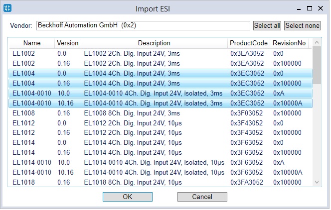
To import an ESI file, please select the menu Tools / Import ESI, then select a valid ESI file on the filesystem, and then select witch slave devices (one or more) you want to import from the ones included in the ESI.
ESI files usually have a .XML extension; but please note that it may happen to have a "main" ESI file, that internally links other XML files with the description of the object dictionary or the list of supported modules.
In this case only the main ESI must be imported.
Master configuration
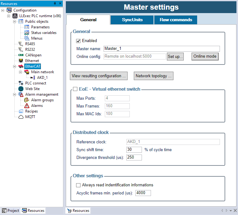
By clicking on the EtherCAT node in Resources tab, the Master settings window will be opened. Here you can configure all the settings of the EtherCAT master.
General tab
- Enabled: globally enables the usage of the EtherCAT network and generate the output ENI file
- Master name: optional description of the EtherCAT master
- Online config / Set up...: configures communication parameters for the Online mode; see specific chapter
- Online config / Online mode: toggles Online mode connection; see specific chapter
- View resulting configuration: shows a preview of the output ENI file
- Network topology: shows a graphical diagram of the physical connections of the EtherCAT slaves
- EoE - Virtual network switch: enables usage of the "Ethernet over EtherCAT" feature, to allow routing of standard Ethernet frames over the EtherCAT network by the EtherCAT master
- Max ports: max number of virtual ethernet ports, that will be the max number of EoE enabled slaves in the network
- Max Frames: internal queue size that can be increased in the event of throughput problems
- Max MAC Ids: must be larger than the maximum number of Ethernet devices ever connected to all systems
- Reference clock: if there are one or more slaves that have DC enabled, will show the slave that will act as sync master for the others (it will be the first of the network)
- Sync shift time: implementation specific parameter that is the advance of Sync0 signal, in percent of cycle time, with respect to the mean send time; try different values if any slave has DC synchronization problems, normally leave as is
- Divergence threshold: maximum allowed divergence of the master timing vs sync master clock
- Always read identification informations: if enabled, all identification data of the slaves (VendorID, ProductCode, RevisionNo, SerialNo) will be read on startup; otherwise, they will be read only if the respective "Check" is enabled on that specific slave settings. Obtained information will be available in the PLC diagnostic structures
SyncUnits tab
A SyncUnit describes a set of process data that should be exchanged synchronously and consistently between the master and one or more slaves; to do this, for each SyncUnit a separate cyclic EtherCAT command will be sent by the master.
Here you can create SyncUnits, and manually assign each slave to a different SyncUnit.
Raw commands tab
Here you can manually enter a list of raw EtherCAT commands that will be cyclically sent by the master, and assign its "Data in" and "Data out" to PLC variables if needed.
Note that this is an advanced feature: usually the cyclic commands are automatically composed from the exchanged variables of the slaves.
Tasks and cycle time
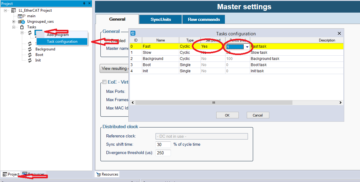
Process data is exchanged between master and slaves with cyclic EtherCAT frames; when the EtherCAT master works together with a PLC, they will be sent on the network synchronously with the Fast PLC task, so it is important to correctly configure the period of it:
to do this, right-click on "Tasks / Fast" in the "Project" tab, choose "Task configuration", set "Set period=Yes" and enter the desired period in milliseconds.
If the EtherCAT configurator is instead used stand-alone without a PLC, there will be an additional "Tasks" tab where you can configure the "Default cycle time" and optionally a list of cyclic tasks, that you can manually assign to SyncUnits to send different cyclic frames with different periods.
Every EtherCAT slave on the network will exchange process data with an I/O cycle time that must be multiple of this base cycle time.
Networks and HotConnect groups
The EtherCAT master always has a Main network under it, that contains all the mandatory slaves in the EtherCAT network.
Each slave with more than 2 ports can also have up to 2 sub-networks, so more complex and non-linear topologies of the EtherCAT network can be created; in this case they will be shown under each slave.
However a number of groups of optional slaves can be also created: they are called HotConnect groups, because each group could not be present at startup and then connected (or disconnected) later from the network:
to add them, right-click on the "EtherCAT" node of the master, and then "Add HotConnect group".
Please also note that each HotConnect group will need a separate SyncUnit, and if DC is used the "sync master" must be in the main network.
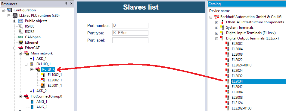
To add an EtherCAT slave under a Network or a HotConnect group, right-click on it and choose "Add", or click on it and then drag&drop the slave from the "Catalog" bar.
If the "Catalog" bar is not visible, you can show it by choosing "View / Tool windows / Catalog" command; all the slaves that are compatible with the type of the selected network will be shown in the catalog.
The "Catalog" bar will shown only the LAST version of each slave device; to show also ALL older versions, use right-click and "Add", and then enable "Show all versions".
Slave configuration
By clicking on each EtherCAT slave node in Resources tab, the Slave settings window will be opened. Here you can configure all the settings of the selected slave.
Right-clicking the slave on the tree also shows additional commands, like "Copy", "Cut", "Move up", "Move down", "Export to file".
General tab
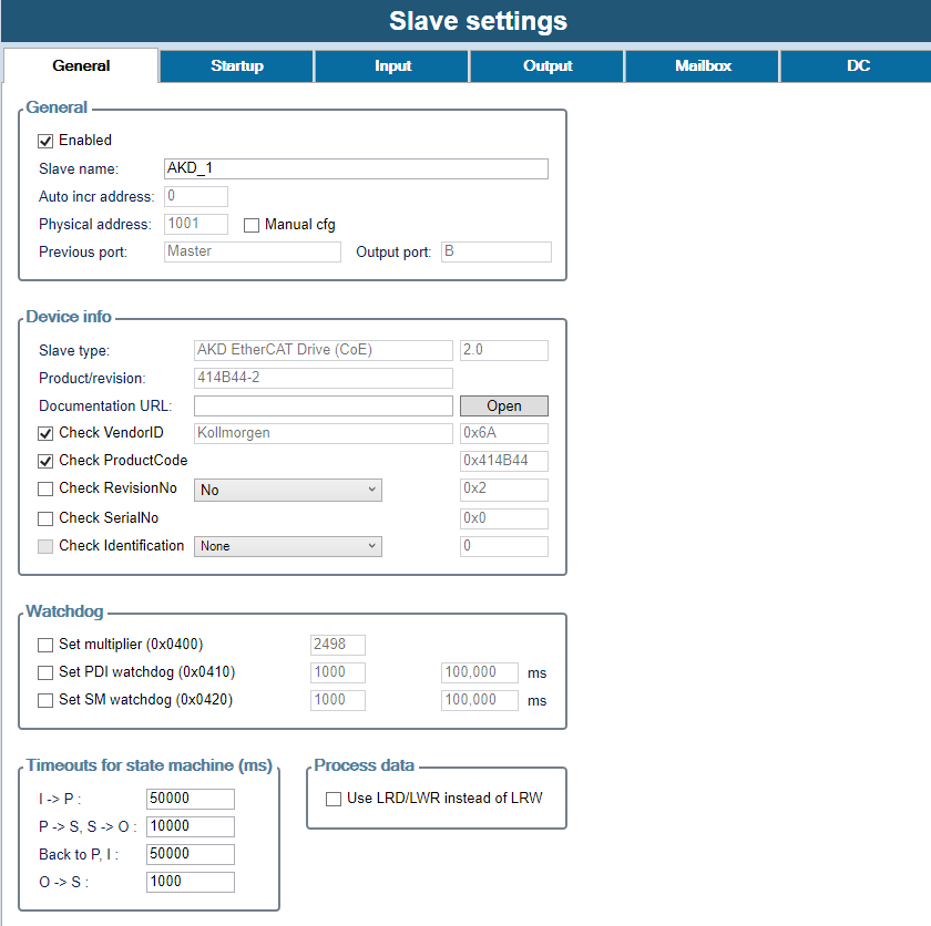
- Enabled: enables the usage of this slave; otherwise will be ignored
- Slave name: unique name of the slave in the EtherCAT network
- Auto incr address: automatically generated address, that will be used internally by EtherCAT commands; first slave has address 0 and then backwards, depending of the slave position in the network
- Physical address: address of the slave that is indipendent from its position on the network; if "Manual cfg" is not enabled, will be automatically generated from 1001, otherwise can be manually entered
- Previous port and Output port: they depend from the network topology; EtherCAT port are usually labelled from A to D (but the EtherCAT frame will follow the ADBC route), and the output port is the last port (in the frame route order) of the same type of the input port. The next slave connected to the output port will be shown as "sibling" in the project tree
- Device info: here you can see various informations from the ESI file, and enable mandatory identity checks (on VendorID, ProductCode, RevisionNo, SerialNo) on the slave at startup
- On the first slave of each HotConnect group, it is mandatory to enable the "Check identification" (with any of the 3 supported methods, tipically the "Station alias", that can be written to EEPROM with Online mode, see below), and optionally the "Check previous slave address" can be enabled to "fix" the position of the group inside the network, after a specific physical address; it this check is not used, the HotConnect group can be positioned anywhere inside the main network
- Watchdog: advanced settings of the watchdog features of the slave; to disable a watchdog set its value to zero
- Timeouts for state machine: timeouts in ms for the various transitions of state machine, between: Init, PreOp, SafeOp, Op
- Use LRD/LWR instead of LRW: if enabled, the optimized LRW command (both read and write, not supported by every slave) will not be used, and two simple LRD (read) and LRW (write) commands will be used instead
Startup tab
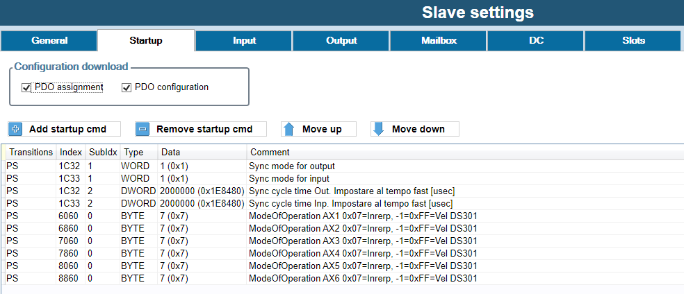
This tab is available only if the slave has CoE support.
- PDO assignment: enable it to allow editing of the "Assigned SM" column in "Input" and "Output" tabs, and then download the assignments at startup
- PDO configuration: enable it to allow editing of PDOs and PDO entries configuration in "Input" and "Output" tabs, and then download the configuration at startup
- Slots configuration: enable it to download the slots configuration at startup (only if the slave has modules/slots)
- Add startup cmd: adds a startup command, that is writing the value of a CoE object at specified state transitions. You can freely enter index/subindex of the CoE object to write, or pick one from object dictionary of the ESI file
Input and Output tab
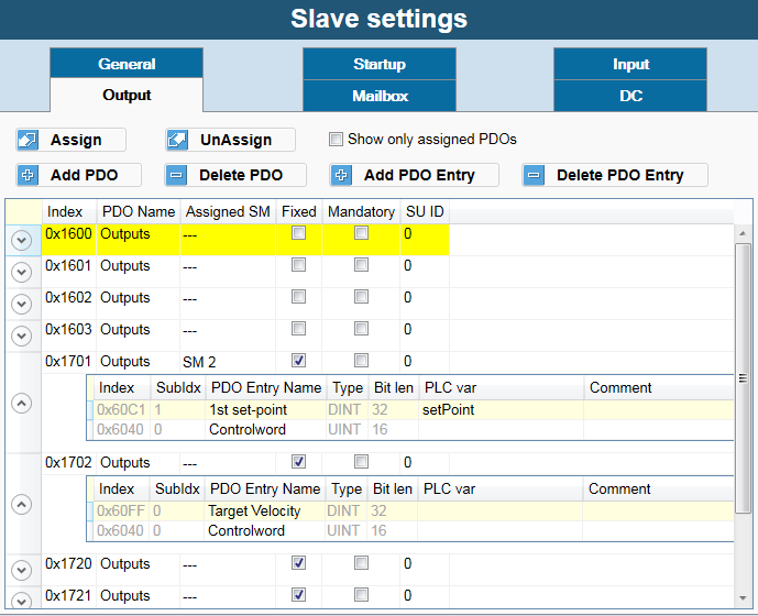
These two tabs (available only if the slave has CoE support) show the actual configuration of PDOs and PDO entries, that compose the process data of the slave, and their assignmento to PLC variables.
Each PDO has an unique Index, and contains a number of PDO Entries; a PDO entry contains a reference to a CoE object to exchange (given its Index and SubIndex in the dictionary of the slave). Only PDOs assigned to a SyncManager will be included in the process image; PDOs not assigned to a SM will not be exchanged at all.
Input PDOs contain data read from the slave to the master, and Output PDOs data written from the master to the slave.
- Assign / UnAssign: choose (or remove) a PLC variable to a specific PDO entry; the PLC variable must already exist in the PLC project, be declared as "Automatic", and have the same size of the PDO entry
- Show only assigned PDOs: if enabled, only PDOs that are assigned to a SyncManager (with the "Assigned SM" column) will be shown in the grid
- Add PDO / Delete PDO: add (or remove) a PDO. "Download PDO configuration" in "Startup" must be enabled
- Add PDO Entry / Delete PDO Entry: add (or remove) a PDO entry in a PDO, that must not be "Fixed"; "Download PDO assignment" in "Startup" must be enabled. You can freely enter index/subindex/type of the CoE object to read or write, or pick one from object dictionary of the ESI file
- Assigned SM: SyncManager that will manage and exchange this PDO
- Fixed: if true, a PDO can not be edited
- Mandatory: if true, a PDO can not be deleted or unassigned from its SM
- PLC var column: instead of choosing an existing PLC variable with the "Assign" button, you can also freely enter its name here; if the variable does not exist, will be automatically created
Mailbox tab
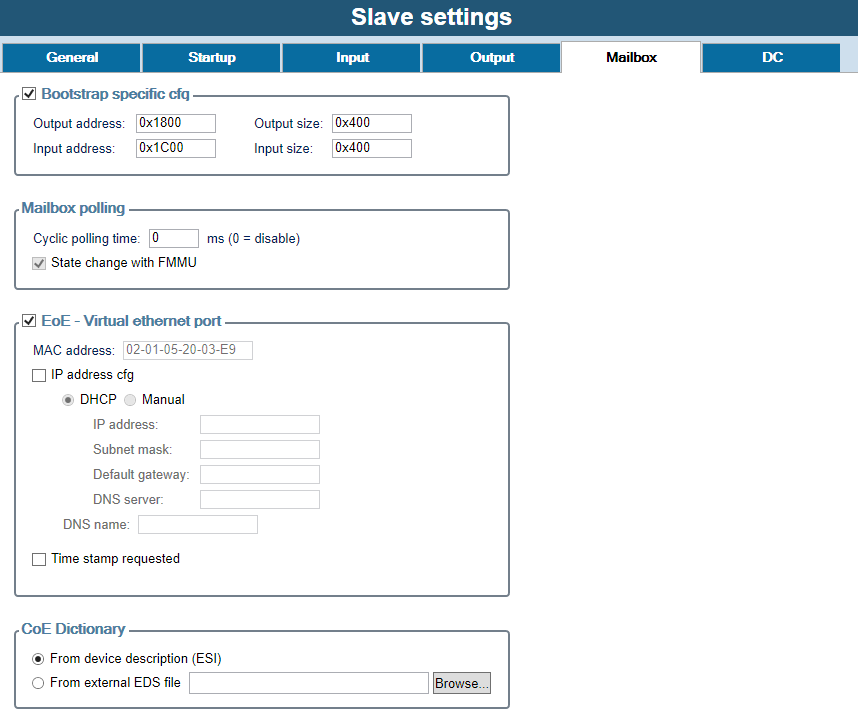
This tab is available only if the slave has mailbox support.
- Bootstrap specific cfg: advanced settings to alter the mailbox configuration at bootstrap phase
- Mailbox polling: advanced settings for mailbox polling
- EoE - Virtual ethernet port: if the slave supports EoE (Ethernet over EtherCAT), here you can configure its IP parameters
- CoE Dictionary: lets you specify an external legacy EDS file to be used for CoE object dictionary, instead of the ESI file
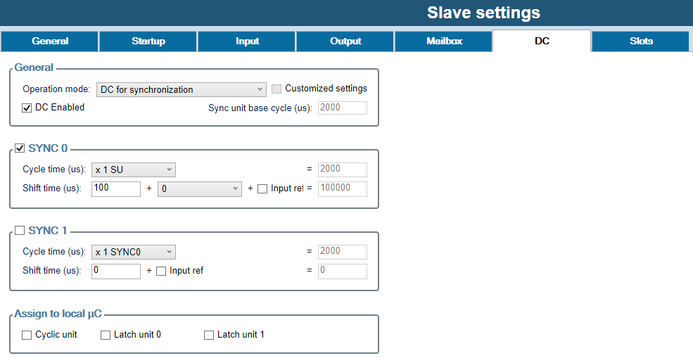
DC tab
This tab is available only if the slave has Distributed clock support.
- Operation mode: you can choose from here any of the predefined DC operation mode (from ESI file); if the predefined mode has been manually modified, "Customized settings" will be checked
- DC Enabled: enables the DC for this slave
- SYNC 0: advanced settings and tuning of the SYNC 0 signal, that is the event when process data is applied: read of the input and actualization of the output
- SYNC 1: advanced settings and tuning of the SYNC 1 signal, that is a device-dependent secondary event
- Assign to local uC: assign the generation of SYNC signal to local CPU, instead of using DC from the network
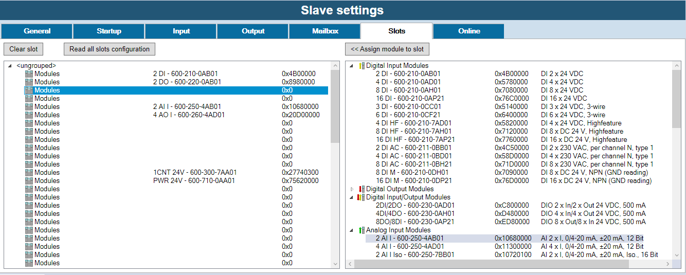
Slots tab
This tab is available only if the slave has modules/slot.
- Slots list (left pane): this is the list of all available slots to be configured on the target, eventually with a grouping
- Modules list (right pane): when you select a slot of the left, here all compatible modules with that slot will be shown. Choose "Assign module to a slot" or double-click it to assign.
- Up: moves up the selected slot, preserving assignments of PLC vars
- Down: moves down the selected slot, preserving assignments of PLC vars
- Read all slots cfg: when Online mode is active, try to auto-detect all the slots configuration from the slave
When a module is assigned to a slot, additional CoE dictionary objects, statup commands, or PDOs could be automatically added to the base slave configuration.
Master online mode
It is possible to connect the EtherCAT configurator to the EtherCAT network, for debugging and diagnostic purposes.
First of all, the Online mode must be configured, by choosing "Online config / Set up..." in the "Master settings" window. You can choose between:
- Remote (GDB): EtherCAT master will be normally running on the remote target, with the EtherCAT network connected to him. This should be the preferred connection mode for debugging, because does not alter the behaviour of the master and of the network
- Gateway: EtherCAT master must not be running on the remote target, and a local EtherCAT master on the PC will be used; the EtherCAT network is physically connected to the remote target, that will only act as a "gateway" to dispatch EtherCAT frames to/from the PC
- Local: a local EtherCAT master on the PC will be used, and the EtherCAT network must be physically to a local Ethernet port of the PC; this requires the installation of the WinPCAP library on the PC, that can be download from here
Once the Online mode has been set up, you can toggle the "Online mode" button to activate it; an additional "Online" tab will appear.
- Network state: shows the actual global state of the network, can be Unknown/OK/Starting/Error
- DC state: shows the actual state of DC (if in use), can be Idle/Synchronizing/WaitingStartTime/Compensating/NotSynchronized/NotUsed
- PLC in sync: shows if the PLC clock is synchronized with the DC (if in use)
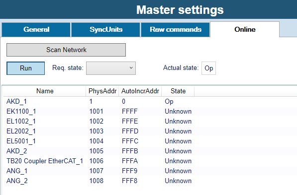
- Run: toggles the running state of the master
- Req. state: changes the requested running state of the master; changing the state of the master will also change the state of ALL slaves
- Actual state: show the actual running state of the master, can be Init/Boot/PreOp/SafeOp/Op
- Target state: show the state that the master is currently trying to reach, can be Init/Boot/PreOp/SafeOp/Op
- Slaves list: shows a resume of all the slaves, with their addresses, actual running state, and identity as actually detected by the master
- Slaves present both in the project and in the real network whose identity is matching are shown in black
- Slaves whose identity is not matching between the project and the real network are shown in red
- Slaves that are detected by the master but missing in the project are shown in blue
- Slaves present in the project but not detected by the master are shown in orange
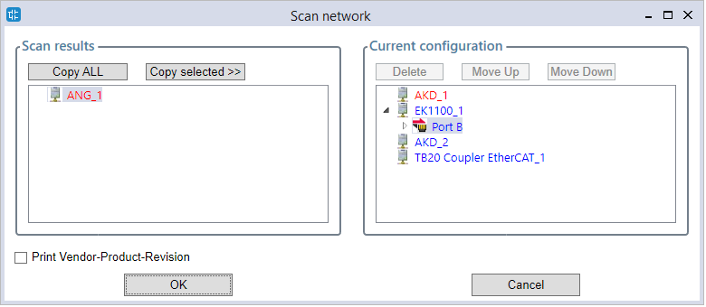
- Scan network: auto-detects all connected EtherCAT slaves on the network. If the current project is empty, all slaves will be automatically added; otherwise a dialog will be shown (see below). Please note that you must already have imported ALL the necessary ESI files in the catalog to successfully complete the network scanning
This is a sample result of the scan: a dialog with two panes, with the scan results on the left and the current configuration on the right, to manually choose which slaves you want to add to the project.
Please note that "Copy selected" will copy the selected slave on the left AFTER the selected slave on the right, so a selection in both panes must be done.
With respect to their position, different slaves are shown in red, matching slaves in black, and missing slaves in blue.
Slave online mode
When Online mode is active, an additional "Online" tab will appear also on each slave.
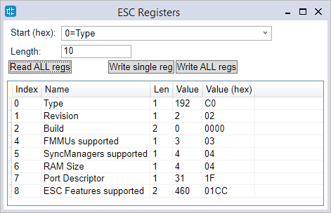
- ESC register access: opens a dialog to read/write values of one or more ESC registers, given its well-known name or freely by index
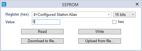
- EEPROM access: opens a dialog to read/write values of EEPROM registers, given its well-known name or freely by index; this is particularly useful to set the "Station alias" if you are using "HotConnect groups"
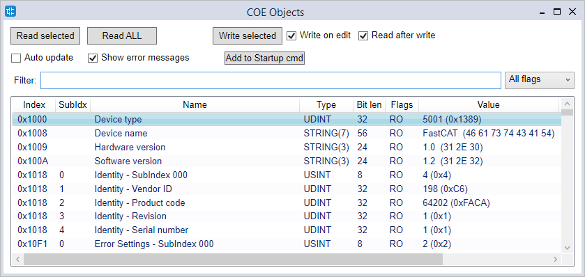
- COE SDO access: opens a dialog to read/write values of one or more CoE objects, by browsing the object dictionary of the slave
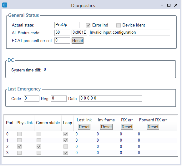
- Diagnostics: opens a dialog that shows diagnostic informations of the slave, internal error codes and physical ports status
- FoE transfer: if the slave supports FoE ("File over EtherCAT"), opens a dialog to execute file upload to the slave; this is can be used for firmware upgrade, parameters upload, etc.
- Req. state: changes the requested running state of the slave; this could be different from the actual state of the master
- Actual state: show the actual running state of the slave
- PDO entries list: shows a resume of all the PDO entries, with their current value; double-click on the "Value" column to manually change the value (just once), or enable the "Forced" column if you want to apply the new value permanently. Works for both input and output PDOs
Diagnostic features
The EtherCAT Master reads two configuration files generated by EtherCAT configurator:
- An ENI file, EtherCAT Network Information, which is a standardized description of the network, that is the output of the EtherCAT configurator
- An XML configuration file, describing the mapping of PLC I/O variables with PDO Entries; this file includes some other master parameters
At start-up, the master first interprets the ENI, which is sufficient to make a network operable, perhaps for debugging purposes, then reads the configuration XML, opens the communication port, and waits to see the link on that port.
As soon as the link is detected, the master:
- it starts sending packets on the network with the timing required
- synchronizes the system clock: in case of configuration with distributedclock, the whole system must be synchronized at network time.
Under normal operating conditions, there are some start-up phases before the network becomes operative: all slave configurations are sent by init commands, these commands carry some specific configurations for each slave. Each slave will step through the following states:
- INIT: initialization phase
- PREOP: pre operational, no data-exchange occur between master and slaves
- SAFEOP: safe operational, only input data from slaves to the master are exchanged
- OP: operational, full data-exchange can happen
If Distributed clock is used, all slaves operating in distributed clock must synchronize their clocks with that of the sync master.
The EtherCAT master must also be synchronized to the network clock, and with it the I/O task cycle and a number of connected activities.
Managing the distributed clock on the master takes place in some phases:
- IDLE: The master clock is completely independent from the slaves
- SYNCHRONIZING: The master is making preliminary measurements to synchronize with the slaves
- WAITING_START_TIME: After the master has synced with the slaves, you have to wait for the START_TIME, which is the first time the slaves implement I/O
- COMPENSATING: If the master clock is synchronous with that of the slaves and after START_TIME has passed, the management goes into this state, which means that the Master is constantly tracking the clocks of the network, in this state typically all slaves are in OP state
- NOT_SYNCHRONIZED: If for any reason the master fails to follow the network clock, then management goes into this state and all the slaves involved go to the SAFE_OP state.
Some master and slave diagnostic structures provide information about the states discussed above inside the PLC.
In these structures and their functions one can refer to a slave in two different ways:
- Using the index, positional on the EtherCAT network, the index starts from 0
- Using a physical address, which can also be selected by the user during configuration
In addition to diagnostic structures, the Master stack can trigger events that can be detected by the PLC application and other plugins in terms of callbacks or callback tasks invocation. Events can typically be:
- the status change of slaves,
- communication errors,
- emergency CoE messages,
- distributed clock status variation,
- resync events, which occur when the slaves or the entire network are ready to go into operating mode,
- and finally the network recovery event, which indicates a reboot of EtherCAT communication to deal with a serious error case.
When an event occurs, that event triggers:
- updating diagnostic structures related to that event
- invoking callback functions for registered plugins
- the execution of the special plc task ECAT_Notify, which can be used to read the updated diagnostic structures
- as an alternative to the ECAT_Notify task, there is also the ECAT_Resync task, that is invoked at the first time that a node or the whole network goes into operating mode: this allows the PLC programmer to perform additional slave configurations by sending and receiving SDOs.
Diagnostic Structures Reference
This chapter describes the diagnostic structures offered by EtherCAT stack and published in the EtherCAT.pll:
- A variable called sysEcatMasterStatus, type ECATMASTERSTATUS, allowing you to have a general view of the status of the EtherCAT network
- A variable called sysEcatSlaveMonitor, type ECATSLAVEMONITOR, which can be placed in Watch on LogicLab to monitor the particular status of any slave
- A set of variables associated with events that can be used by the PLC to react to changes in the status and errors of the EtherCAT network:
- sysECATEventId, type ECATEVENTID, containing the ID of the last encountered event
- sysECATEmcyEvent, type ECATEMCYEVENT: this structure contains information about the last Emergency event sent by a CoE slave
- sysECATErrorEvent, type ECATERROREVENT: this structure gives information about the last error event detected on the EtherCAT
- sysECATNetworkRecoveryEvent, of type ECATNETWORKRECOVERY: this structure refers to the last event of NetworkRecovery
- sysECATNodeStatusChangedEvent, of type ECATNODESTATUSEVENT: this structure gives information about the last change of status of a slave
- sysECATDCStatusChangedEvent, of type ECATDCSTATUSEVENT: this structure gives information about the last variation of the master state, related to its synchronization with the Distributed Clock
- as shown in the overview, these variables can be consulted within the special tasks ECAT_Notify and ECAT_Resync, they can also be watched in LogicLab for more detailed information about events occured.
- A set of functions to access the slave diagnostic structures, containing the same information as the SlaveMonitor; they can refer to the physical address of the node (ByAddress version), or to the location index of the node in the network, starting from index 0 (ByIndex version):
- sysECAT_GetSlaveDiag [ByAddress | ByIndex]: Returns a pointer to the diagnostic structure (@ECATSLAVESTATUS), or NULL if the function fails
- sysECAT_GetSlaveCfg [ByAddress | ByIndex]: Returns a boolean value whether the required slave has been configured or not
- sysECAT_GetSlavePres [ByAddress | ByIndex]: Returns a boolean value indicating the presence, if the slave is physically connected
- sysECAT_GetSlaveState [ByAddress | ByIndex]: Returns the slave network status (ECATSTATE)
- Two function blocks for read and write SDO; they can be used to read or write objects to perform checks from PLC, or to do auxiliary configurations after the network has entered the operating mode:
- sysECAT_Sdo_Read
- sysECAT_Sdo_Write
For further details and descriptions of all the fields, please see the "Properties" window inside LogicLab of each object of the EtherCAT.pll library.
Troubleshooting and FAQ
What happens if the drives_clock field of the diagnostic structure of the master becomes FALSE?
This field indicates that a timeout has occurred such that the LLExec clock has been released from the EtherCAT Clock: typically this can happen when communication between the Master and the first slave fails due to, for example, the first cable interrupted or of a fault in the first slave.
What happens if one or more nodes are not present or stop working?
In the event that the fault is located in the first slave, the most common symptom is that the drives_clock flag in the master's structure becomes false.
In the case of fault located in other nodes, it depends on whether they are present during the network startup phase or not:
if there are missing nodes in the startup phase the network will not go beyond the INIT state, you can use the SlaveMonitor to see which is the first node that presented an error or is missing.
In case the network has already gone into operational, the field network_ok of the master becomes false, you can use the SlaveMonitor to check which slave is missing, or have submitted an error.
Attention: if a slave stops working, the other slaves may remain in operating status: it is therefore the task of the application to reset the outputs or take appropriate actions.
What happens if the network_ok field of the diagnostic structure of the master becomes FALSE?
network_ok becomes TRUE when all the slaves go into operating mode, it returns FALSE if a slave is no longer present, or has shown an error.
You can use the SlaveMonitor, to be able to identify the slave that is not present, or the one that has shown an error.
What happens if less slaves are configured than those actually present in the network?
The network will not go into operation, apparently all the slaves do not report errors, so you can look at the sysECATErrotEvent structure to check if there are any errors not related to the configured slaves:
in this case you will see the error K10063_MASTER_SLAVES_COUNT
